Working gas circulation type engine

Inactive Publication Date: 2015-05-07
TOYOTA JIDOSHA KK
9 Cites 11 Cited by

AI-Extracted Technical Summary

Problems solved by technology

As described above, presence of the water vapor in the working gas is the cause of reduction of the engine thermal efficiency.
However, in order to increase the radiation heat amount in the radiator, upsizing the radiator an...

Method used

[0100]As above, according to the present embodiment, by executing the stratification operation, the working gas with a high water vapor partial pressure in the gas can be introduced into the condenser 30. Therefore, the pressure difference between the water vapor partial pressure in the working gas discharged from the combustion chamber 14 and the saturated water vapor partial pressure can be made large. Accordingly, in the condenser 30, a larger amount of condensed water can be generated. Further, if the stratification operation is executed, the working gas layer with a high working gas concentration can be formed in the vicinity of the wall surface of the combustion chamber 14 on the occasion of the combustion stroke. Accordingly, a reaction of H2 and O2 in the vicinity of the wall surface can be restrained, and cooling loss can be reduced. Therefore, the thermal efficiency also can be significantly improved...

Benefits of technology

[0060]According to the first invention, by executing the stratification operation, a layer of the reactant and a layer of the working gas can be formed in the combustion chamber before reaction. Therefore, in the combustion chamber after the reaction, a layer with a high concentration of generated water vapor, and a layer with a high concentration of the working gas can be formed. Here, the amount of water vapor that can be separated and removed by the water vapor separating and removing means becomes larger as the pressure difference between the water vapor partial pressure in the working gas which is introduced therein and a saturated water vapor partial pressure is larger. Further, the water vapor partial pressure in the working gas becomes higher in accordance with increase in the water vapor concentration. In this regard, according to the first invention, the layer with a high water vapor concentration can be formed, and therefore, the working gas with a high water vapor partial pressure can be discharged to the circulation path. Accordingly, in the water vapor separating and removing means, a larger amount of water vapor can be separated and removed.
[0061]According to the second invention, by executing the stratification operation, the inner layer formed from the reactant and the outer layer formed from the working gas can be formed in the combustion chamber before reaction. Therefore, in the combustion chamber after the reaction, the inner layer with a high concentration of the generated water vapor and the outer layer with a high concentration of the working gas can be formed. Accordingly, similarly to the above described first invention, a larger amount of water vapor can be separated and removed in the water vapor separating and removing means. Further, according to the second invention, the reaction can be caused to proceed in the inner side of the combustion chamber. In other words, reaction in the vicinity of the wall surface of the combustion chamber can be restrained from proceeding. Accordingly, cooling loss from the wall surface of the combustion chamber can...

Abstract

In a stratification operation, O2 is injected from an oxygen injector during valve opening of an intake valve. Therefore, the injected O2 flows into a combustion chamber immediately after the injection, and forms a layer having a constant spread in the combustion chamber. Meanwhile, the working gas in the combustion chamber forms such a layer as to cover the O2 layer on a wall surface of the combustion chamber in conjunction with formation of the O2 layer. In other words, in the combustion chamber, an inner layer with a high O2 concentration and an outer layer with a high working gas concentration are respectively formed.

Application Domain

Internal combustion piston enginesNon-fuel substance addition to fuel +6

Technology Topic

InjectorValve opening +6

Image

  • Working gas circulation type engine
  • Working gas circulation type engine
  • Working gas circulation type engine

Examples

  • Experimental program(10)

Example

[0089]First, embodiment 1 of the present invention will be described with reference to FIG. 1 to FIG. 5. FIG. 1 is a diagram showing a configuration of a working gas circulation type engine of embodiment 1. As shown in FIG. 1, the working gas circulation type engine of the present embodiment includes an engine main body 10. The engine main body 10 is a so-called four stroke engine, and has at least one cylinder. In the cylinder, a combustion chamber 14 is defined by a piston 12. Further, the cylinder is provided with a hydrogen injector 16 that injects high-pressure H2 toward the combustion chamber 14.
[0090]Further, the working gas circulation type engine of the present embodiment includes an intake port 18 and an exhaust port 20 that communicate with the combustion chamber 14. Between the intake port 18 and the exhaust port 20, a connection passage 22 that connects the intake port 18 and the exhaust port 20. The intake port 18 is provided with an oxygen injector 24 that injects high-pressure O2, and an intake valve 26 that opens/closes an inlet port of the combustion chamber 14. The exhaust port 20 is provided with an exhaust valve 28 that opens/closes an exhaust port of the combustion chamber 14.
[0091]Further, the working gas circulation type engine of the present embodiment includes a condenser 30. The condenser 30 is provided halfway through the connection passage 22, and cools and liquefies water vapor in the working gas that flows in the connection passage 22. The condenser 30 includes a cooling water channel 32 for passing the cooling water through an inside thereof. The cooling water channel 32 is connected to a radiator 34, and the cooling water is cooled by the radiator 34. Further, the condenser 30 includes an exhaust path 36 that discharges condensed water generated in the condenser 30 to an outside.
[0092]Further, the working gas circulation type engine of the present embodiment includes an ECU 50 as a control device. The ECU 50 is connected to the hydrogen injector 16, the oxygen injector 24, the intake valve 26, the exhaust valve 28 and the like. The ECU 50 executes a stratification operation that will be described later and the like by driving the respective actuators while detecting operation information of the engine main body 10 by a sensor system.
Feature of Embodiment 1
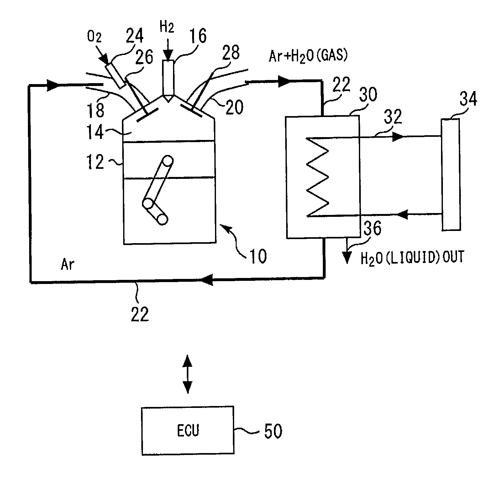
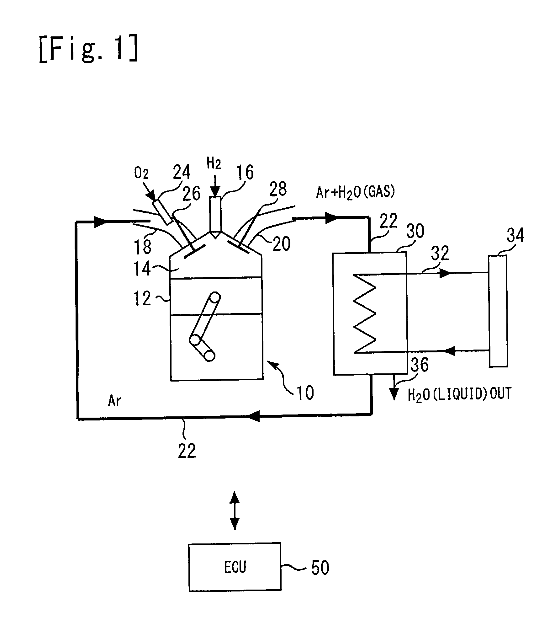
[0093]In the present embodiment, a working gas is filled in the combustion chamber 14, the intake port 18, the exhaust port 20 and the connection passage 22. A flow of the working gas will be described in combination with operations of the piston 12, the intake valve 26 and the exhaust valve 28. The working gas in the intake port 18 flows into the combustion chamber 14 in conjunction with a descend of the piston 12 while the inlet port of the combustion chamber 14 is opened (namely, during valve opening of the intake valve 26) (an intake stroke). In the intake stroke, O2 from the oxygen injector 24 also flows into the combustion chamber 14, in addition to the working gas. The piston 12 ascends after reaching a bottom dead center thereof. Thereupon, the working gas and 02 that flow into the combustion chamber 14 are compressed with the working gas which is already filled in the combustion chamber 14 (a compression stroke). Thereafter, H2 is injected from the hydrogen injector 16 in a vicinity of a top dead center, and the H2 reacts with O2. By the reaction heat, the working gas in the combustion chamber 14 expands to press the piston 12 downward (a combustion stroke). The piston 12 ascends again after reaching the bottom dead center thereof. On this occasion, if the exhaust valve 28 is operated to open the exhaust port of the combustion chamber 14, the working gas in the combustion chamber 14 is discharged to the exhaust port 20 (an exhaust stroke). The discharged working gas flows through the exhaust port 20 and the connection passage 22 to reach the intake port 18.
[0094]In the present embodiment, Ar is used as the working gas. Use of Ar can improve thermal efficiency. The reason thereof will be described with reference to FIG. 2 and FIG. 3. FIG. 2 is a diagram showing specific heat ratios of various gases. As shown in FIG. 2, Ar has a higher specific heat ratio than H2, N2, O2 and H2O. Further, FIG. 3 is a diagram showing a relationship of a compression ratio ε and thermal efficiency ηth. As shown in FIG. 3, under a condition that the compression ratio c is constant, the thermal efficiency 11th becomes higher as the specific heat ratio κ becomes higher. Accordingly, if Ar with the high specific ratio κ is used as the working gas, the thermal efficiency can be improved. Note that with any gas that has a specific heat ratio higher than air and is inert to the reaction in the combustion chamber, the operational effect similar to the operational effect with Ar can be obtained. Therefore, the inert gas also can be used in place of Ar or together with Ar.
[0095]Incidentally, the working gas that is discharged from the combustion chamber 14 contains water vapor generated by the reaction of H2 and O2. The water vapor is condensed and liquefied in the condenser 30. However, condensation and liquefaction in the condenser 30 are limited. Therefore, in the condenser 30, the water vapor in the working gas cannot be completely separated and removed. The reason thereof will be described with reference to FIG. 4. FIG. 4 is a saturated water vapor partial pressure curve. As shown in FIG. 4, when a water vapor partial pressure in the gas, for example, at 40° C. is higher than a saturated vapor partial pressure, water vapor corresponding to pressure differences thereof (Pa, Pb) is liquefied. In other words, water vapor corresponding to saturated water vapor partial pressure (P1) always remains in the gas. The remaining phenomenon also applies to the inside of the condenser 30. Accordingly, a constant amount of water vapor corresponding to a gas temperature flows to a downstream side from the condenser 30.
[0096]Note, however, attention should be paid to the point that the pressure difference in FIG. 4 is Pa>Pb. As described above, in the condenser 30, the water vapor corresponding to the above described pressure difference can be liquefied. Namely, if the above described pressure difference is larger, a larger amount of condensed water can be generated. By focusing on this point, in the present embodiment, a stratification operation of making the working gas concentration in the combustion chamber 14 in the compression stroke higher in the vicinity of a wall surface thereof than in a center portion thereof is executed.
[Stratification Operation]
[0097]FIG. 5 is a diagram for explaining the stratification operation. In the stratification operation, during valve opening of the intake valve 26, O2 is injected from the oxygen injector 24. Therefore, the injected O2 flows into the combustion chamber 14 immediately after the injection, and forms a layer having a constant spread in the combustion chamber 14 (A in FIG. 5). On the other hand, in conjunction with formation of the O2 layer, the working gas in the combustion chamber 14 forms such a layer as to cover the O2 layer in the wall surface of the combustion chamber 14 (B in FIG. 5). Namely, in the combustion chamber 14, an inner layer (A in FIG. 5) with a high O2 concentration, and an outer layer (B in FIG. 5) with a high working gas concentration are respectively formed.
[0098]The inner layer which is formed in this manner also keeps a stratified state in the above described compression stroke. Therefore, the water vapor that is generated in the subsequent combustion stroke also forms a layer having a constant spread similarly to O2. Namely, in the combustion chamber 14 in the combustion stroke, an inner layer with a high water vapor concentration and an outer layer with a low water vapor concentration are formed. The working gas including the inner layer formed in this manner has a high water vapor partial pressure in the gas. Therefore, if the working gas in this state is introduced into the condenser 30, the above described pressure difference can be made large, and therefore, a larger amount of condensed water can be generated in the condenser 30.
[0099]Here, as comparison with the stratification operation, a homogenization operation will be described. A homogenization operation is control that homogenizes the working gas concentration distribution in the combustion chamber 14 during the compression stroke, and is control that is different from the above described stratification operation. In the homogenization operation, O2 injection form the oxygen injector 24 is started while the inlet port of the combustion chamber 14 is closed (namely, before valve opening of the intake valve 26). Thereupon, the injected O2 temporarily stays in the intake port 18. The staying O2 mixes with the working gas and is brought into a homogenized state, flows into the combustion chamber 14 in conjunction with valve opening of the intake valve 26, and is compressed. Namely, the O2 concentration distribution in the combustion chamber 14 becomes substantially uniform. Therefore, the concentration distribution of the water vapor generated in the combustion stroke also becomes substantially uniform. Therefore, even if the working gas in this state is introduced into the condenser 30, the amount of the condensed water that is generated is small.
[0100]As above, according to the present embodiment, by executing the stratification operation, the working gas with a high water vapor partial pressure in the gas can be introduced into the condenser 30. Therefore, the pressure difference between the water vapor partial pressure in the working gas discharged from the combustion chamber 14 and the saturated water vapor partial pressure can be made large. Accordingly, in the condenser 30, a larger amount of condensed water can be generated. Further, if the stratification operation is executed, the working gas layer with a high working gas concentration can be formed in the vicinity of the wall surface of the combustion chamber 14 on the occasion of the combustion stroke. Accordingly, a reaction of H2 and O2 in the vicinity of the wall surface can be restrained, and cooling loss can be reduced. Therefore, the thermal efficiency also can be significantly improved.
[0101]Note that while in the above described embodiment 1, the hydrogen injector 16 is provided in the cylinder of the engine main body 10, and the oxygen injector 24 is provided in the intake port 18, the disposition spots of these injectors can be changed. More specifically, the installation spot of the hydrogen injector 16 and the installation spot of the oxygen injector 24 may be replaced. Further, the installation spots of both the injectors may be in the intake port 18, or may be in the cylinder of the engine main body 10.
[0102]However, when the installation spots of both the injectors are replaced with each other, H2 needs to be injected from the hydrogen injector 16 during valve opening of the intake valve 26 in the above described stratification operation. Further, when the installation sports of both the injectors are both set at the intake port 18, H2 and O2 need to be injected from the both injectors during valve opening of the intake valve 26 in the above described stratification operation. When the installation spots of both the injectors are both set at the cylinder of the engine main body 10, H2 and O2 need to be injected during a time period until the combustion stroke from the intake stroke, in the above described stratification operation.
[0103]Namely, any combination of injector disposition which can form H2 and O2 layers and the working gas layer separately, in the combustion chamber 14 immediately before the combustion stroke, and the stratification operation corresponding to the injector disposition, can be applied as a modification of embodiment 1 described above.
[0104]Note that in embodiment 1 described above, the intake port 18, the exhaust port 20 and the connection passage 22 correspond to the “circulation path” in each of the above described first and second inventions, the combustion chamber 14 corresponds to the “combustion chamber” in each of the above described first and second inventions, the condenser 30 corresponds to the “water vapor separating and removing means” in each of the above described first and second inventions, respectively.
[0105]Further, in embodiment 1 described above, the ECU 50 executes the stratification operation, whereby the “stratification operation execution means” in each of the above described first and second inventions is realized.
[0106]Further, in embodiment 1 described above, the intake valve 26 corresponds to the “inlet port opening and closing means” in the above describe third invention, the oxygen injector 24 corresponds the “reactant supply means” in the above described third invention, and the ECU 50 corresponds to the “control means” in the above described third invention, respectively.

Example

Embodiment 2
[0107]Next, embodiment 2 of the present invention will be described with reference to FIG. 6. The present embodiment differs from embodiment 1 described above in that the disposition spot of the oxygen injector 24 is specified. Namely, a configuration of an engine, a basic flow of the working gas, and a stratification operation are common to the engine of embodiment 1 described above. Therefore, hereinafter, the above described difference will be mainly described, and explanation of the points common to embodiment 1 described above will be simplified or omitted.
Feature of Embodiment 2
[0108]FIG. 6 is a diagram for describing a feature part of embodiment 2. As shown in FIG. 6, the intake port 18 branches at an upstream side of the combustion chamber 14. More specifically, the intake port 18 is configured by an intake port 18a branching to an inlet port 14a side of the combustion chamber 14, and an intake port 18b branching to an inlet port 14b side of the combustion chamber. Further, a demarcation passage 19a that partially demarcates parts of the intake ports 18a and 18b is formed halfway between the intake ports 18a and 18b. The demarcation passage 19a is provided with the oxygen injector 24.
[0109]In the present embodiment, the intake port 18 is configured as described above, and therefore, a working gas channel and an O2 channel in the intake port 18 can be configured separately. Namely, the working gas can be caused to flow into the intake ports 18a and 18b and O2 from the oxygen injector 24 can be caused to flow into the demarcation passage 19a to be caused to flow into the combustion chamber 14. Therefore, in the intake port 18, the working gas and O2 can be reliably prevented from mixing with each other. Further, in the present embodiment, the demarcation passage 19a is formed as described above, and therefore, with respect to O2 that flows into the combustion chamber 14, a layer having a constant spread can be formed in a center portion thereof. Consequently, according to the present embodiment, an inner layer with a high O2 concentration can be reliably formed in the center portion of the combustion chamber 14. Therefore, an effect similar to the effect of embodiment 1 described above can be reliably obtained.
[0110]Note that in embodiment 2 described above, the demarcation passage 19a corresponds to the “demarcation channel” in the above described eighth invention.

Example

Embodiment 3
[0111]Next, embodiment 3 of the present invention will be described with reference to FIG. 7. The present embodiment differs from embodiment 1 described above in that the disposition spot of the oxygen injector 24 is specified, and the intake port 18b is configured by a helical port. Namely, a configuration of an engine, a basic flow of the working gas, and a stratification operation are common to the engine of embodiment 1 described above. Therefore, hereinafter, the above described differences will be mainly described, and explanation of the points common to embodiment 1 described above will be simplified or omitted.
Feature of Embodiment 3
[0112]FIG. 7 is a diagram for describing a feature part of embodiment 3. As shown in FIG. 7, the intake port 18 is configured by the intake port 18a branching to the inlet port 14a side, and the intake port 18b branching to the inlet port 14b side. The intake port 18b is a so-called helical port that is formed into a helical shape so as to generate a swirl flow in the combustion chamber 14. In contrast with this, the intake port 18a is a so-called straight port. The intake port 18a is provided with the oxygen injector 24.
[0113]The working gas that flows in the connection passage 22 flows into the combustion chamber 14 via the intake ports 18a and 18b. Note that since in the present embodiment, the intake port 18b is configured by a helical port, the working gas passing through the intake port 18b forms a swirl flow to flow into the combustion chamber 14, and forms an outer layer with a high working gas concentration along the wall surface thereof. Meanwhile, an O2-containing working gas passing through the intake port 18a forms an inner layer having a constant spread in the center portion in the combustion chamber 14, due to formation of the outer layer. Consequently, according to the present embodiment, the inner layer with a high O2 concentration can be formed in the center portion of the combustion chamber 14. Therefore, an effect similar to the effect of embodiment 1 described above can be obtained.

PUM

no PUM

Description & Claims & Application Information

We can also present the details of the Description, Claims and Application information to help users get a comprehensive understanding of the technical details of the patent, such as background art, summary of invention, brief description of drawings, description of embodiments, and other original content. On the other hand, users can also determine the specific scope of protection of the technology through the list of claims; as well as understand the changes in the life cycle of the technology with the presentation of the patent timeline. Login to view more.

Similar technology patents

Luminous unit and luminous module thereof

Owner:XIAMEN SANAN OPTOELECTRONICS CO LTD

Classification and recommendation of technical efficacy words

  • improve thermal efficiency

Thermal power plant

InactiveUS20060185366A1improve thermal efficiencyminimum energy loss
Owner:SIEMENS AG

Method and apparatus for improving efficiency of high-power linear amplifier

InactiveUS6418304B1improve thermal efficiency and reliabilityimprove thermal efficiency
Owner:LUCENT TECH INC +1

Heater for electrically heating cigarettes

ActiveCN103533684AIncrease heating contact areaImprove thermal efficiency
Owner:HONGTA TOBACCO GRP

Adiabatic, two-stroke cycle engine having novel combustion chamber

InactiveUS6089195Aimprove thermal efficiencyreduce heat loss and friction
Owner:LOWI JR ALVIN
Why Eureka
Try Eureka