
Fabry-Perot interferometer and a method for producing the same

a technology of fabryperot and interferometer, which is applied in the direction of interferometer, manufacturing tools, instruments, etc., can solve the problems of inability to provide interferometers with very small gaps, similar deficiencies, and limitations of micromechanical technology, so as to avoid or reduce the disadvantages of the prior, small gap, and moderate weight

Active Publication Date: 2015-05-07
TEKNOLOGIAN TUTKIMUSKESKUS VTT
View PDF9 Cites 9 Cited by
  • Summary
  • Abstract
  • Description
  • Claims
  • Application Information

AI Technical Summary

Benefits of technology

The present invention provides a Fabry-Perot interferometer with a small, uniform gap between the mirrors that can be controlled with a moderate weight and manufacturing cost. An intermediate structure is used to decrease bending of the mirror and facilitate a small gap between the optically functional areas of the mirrors. The controllable actuator can control the width of the gap. The interferometer has electrodes in the mirrors for capacitive measurement of the gap width. Overall, this invention overcomes disadvantages of prior art and provides a more efficient and cost-effective way to produce the interferometer.

Problems solved by technology

However, there are some limitations related to the micromechanical technology.
Fabry-Perot interferometers are also commonly made with liquid crystal technology, but this technology has similar deficiencies.
Some disadvantages are related to the prior known Fabry-Perot interferometers in which controllable actuators are used.
In other words, it is not possible to provide interferometers with very small gaps.
There is another problem related to achieving a uniform gap between the mirrors.
The shrinkage of the glue tends to cause bending of the mirrors, whereby the size of the gap between the mirrors becomes non-uniform.
When the gap is not uniform with a required accuracy, this further causes the functional wavelength band of the Fabry-Perot interferometer to become wider and shifted.
The bending also increases the risk of the mirrors touching each other, and to avoid such touching of mirrors it is necessary to use a larger average gap between the mirrors.
However, the use of thick mirror substrates causes the weight and manufacturing costs of the Fabry-Perot interferometer to become high.
This may, for example, cause decreasing of signal-to-noise ratio when a Fabry-Perot interferometer is used in measuring radiation with low intensity.

Method used


Image

  • Fabry-Perot interferometer and a method for producing the same
  • Fabry-Perot interferometer and a method for producing the same
  • Fabry-Perot interferometer and a method for producing the same

Examples


Embodiment Construction

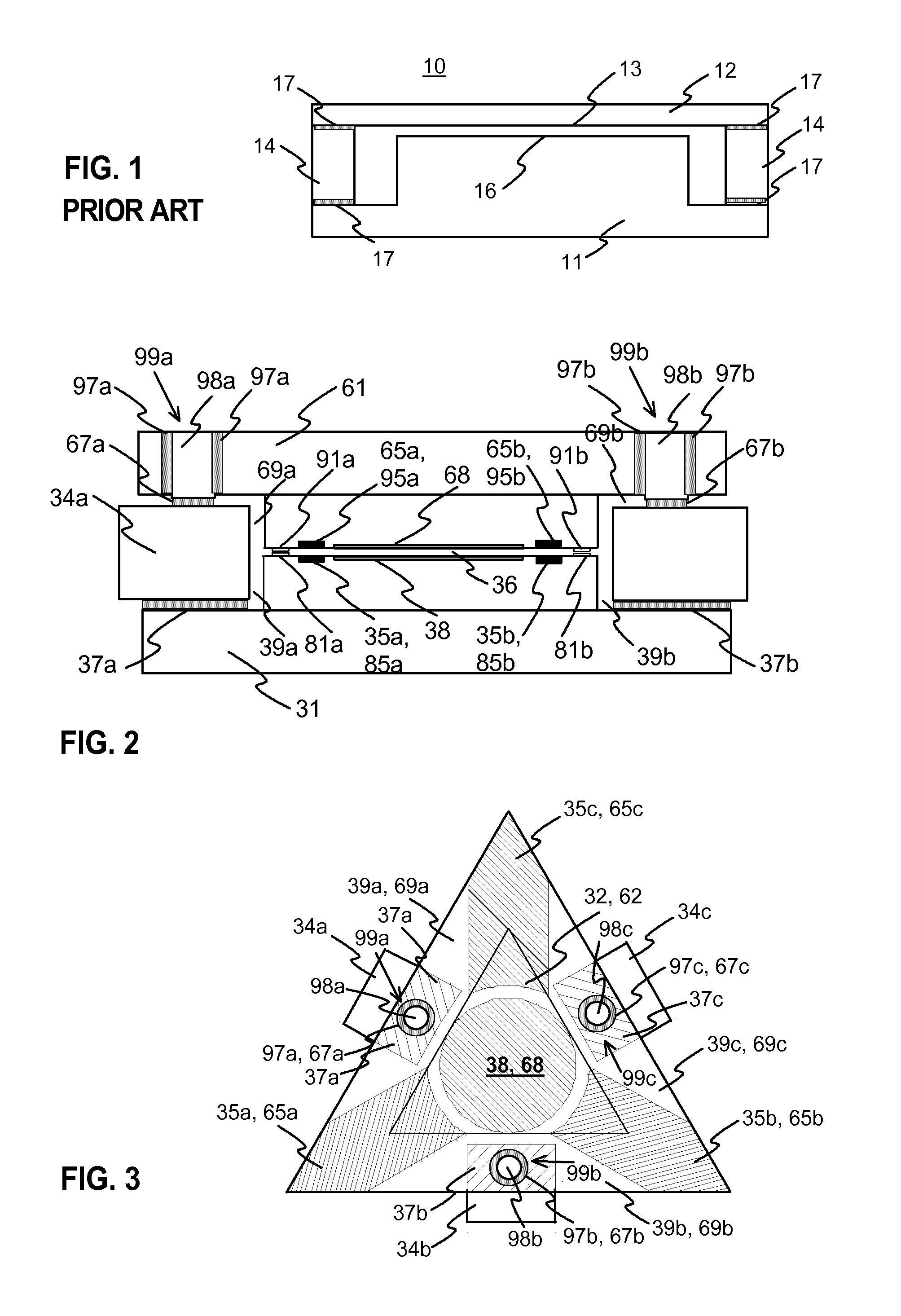
[0046]FIG. 1 was described in the prior art description above.

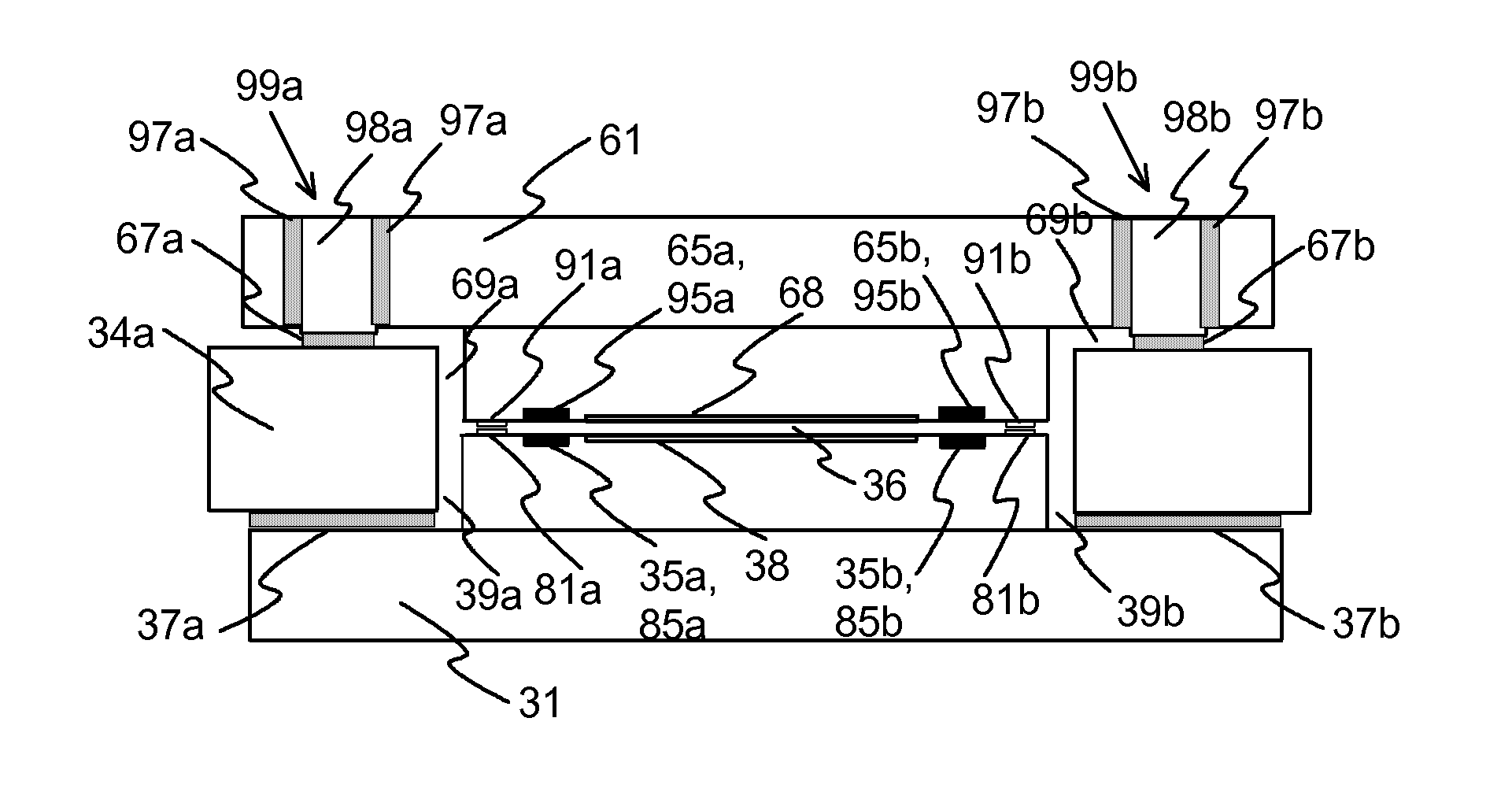
[0047]FIG. 2 illustrates a cross section view of an exemplary Fabry-Perot interferometer according to the invention. FIG. 3 illustrates an exemplary triangular-shape Fabry-Perot intereformeter. The parts of the interferometer are shown translucent so that the parts are better visible in the FIG. 3.

[0048]The illustrated interferometer has two mirrors, a first mirror 31 and a second mirror 61. The mirrors have a substrate of silicon, for example. In the middle of the mirror there is the circular area 38, 68, wherein there is a partially reflecting surface layer in both mirrors, and which area is used for the optical functionality of the interferometer. Reflecting layers are located at those mirror surfaces which are against the gap 36 between the mirrors. The reflecting layer can be e.g. silver, which is attached to the substrate with titanium, for example. There may also be a protective layer of silicon dioxide on metal mi...


PUM

PropertyMeasurementUnit
frequencyaaaaaaaaaa
thicknessaaaaaaaaaa
thicknessaaaaaaaaaa

Abstract

The invention relates to a Fabry-Perot interferometer and a method for producing the same. More specifically, the invention relates to Fabry-Perot interferometers which are controllable with one or several actuators, such as piezoelectric, electrostrictive or flexoelectric actuators. In prior art technology there is a problem to achieve a sufficiently small and uniform gap between mirrors. In the present invention an intermediate structure (85a, 85b, 95a, 95b, 81a, 81b, 91a, 91b, 98a, 98b) is used between a mirror and an actuator or between two mirrors. The method of production also includes measuring the width distribution of the gap in several phases, and providing pre-actuation of actuators.

Description

TECHNICAL FIELD[0001]The invention relates to a method for producing a Fabry-Perot interferometer, and a Fabry-Perot interferometer. More specifically, the invention relates to Fabry-Perot interferometers which are controllable with actuators, such as piezoelectric, electrostrictive or flexoelectric actuators.BACKGROUND TECHNOLOGY[0002]Fabry-Perot interferometers are used as optical filters and in spectroscopic sensors, for example. The Fabry-Perot interferometer is based on parallel beam splitter mirrors, whereby a Fabry-Perot cavity is formed into a gap between the mirrors. The pass band wavelength of a Fabry-Perot interferometer can be controlled by adjusting the distance between the mirrors i.e. the width of the gap. It is common to use micromechanical technology for producing Fabry-Perot interferometers because of low production costs of the technology. However, there are some limitations related to the micromechanical technology. The adjustment range of the mirror position is ...

Claims


Application Information

Patent Timeline
Patent Type & Authority Applications(United States)
IPC IPC(8): G01B9/02
CPCG01B2290/25G01B9/02G01J3/26Y10T29/49826G02B26/001G02B5/284
Inventor ANTILA, TAPANIMAKYNEN, JUSSIHOLMLUND, CHRISTERANTILA, JARKKOOLLILA, JYRKISAARI, HEIKKI
Owner TEKNOLOGIAN TUTKIMUSKESKUS VTT
Learn More