Materials and Process Using a Three Dimensional Printer to Fabricate Sintered Powder Metal Components

Inactive Publication Date: 2015-05-07
AMERICAN HAKKO PRODS
View PDF0 Cites 108 Cited by
  • Summary
  • Abstract
  • Description
  • Claims
  • Application Information

AI Technical Summary

Benefits of technology

[0007]The present invention is directed to a method, process and feedstock material for producing sintered powder metallic parts according to computer-generated design data, starting with the fabrication of a powder metal and polymer/plastic binder green state article using a 3D printer. After formation of the green state article, the article is subjected to de-binder processing to remove the polymer/plastic binder component, and then sintering to fuse the powder metal to a net shape article. Appro

Problems solved by technology

However, both technologies still have a disadvantage as compared to the much more expensive and time consuming powder bed laser sintering technologies that have been used to form net shape cer

Method used


Image

  • Materials and Process Using a Three Dimensional Printer to Fabricate Sintered Powder Metal Components
  • Materials and Process Using a Three Dimensional Printer to Fabricate Sintered Powder Metal Components
  • Materials and Process Using a Three Dimensional Printer to Fabricate Sintered Powder Metal Components

Examples


Example

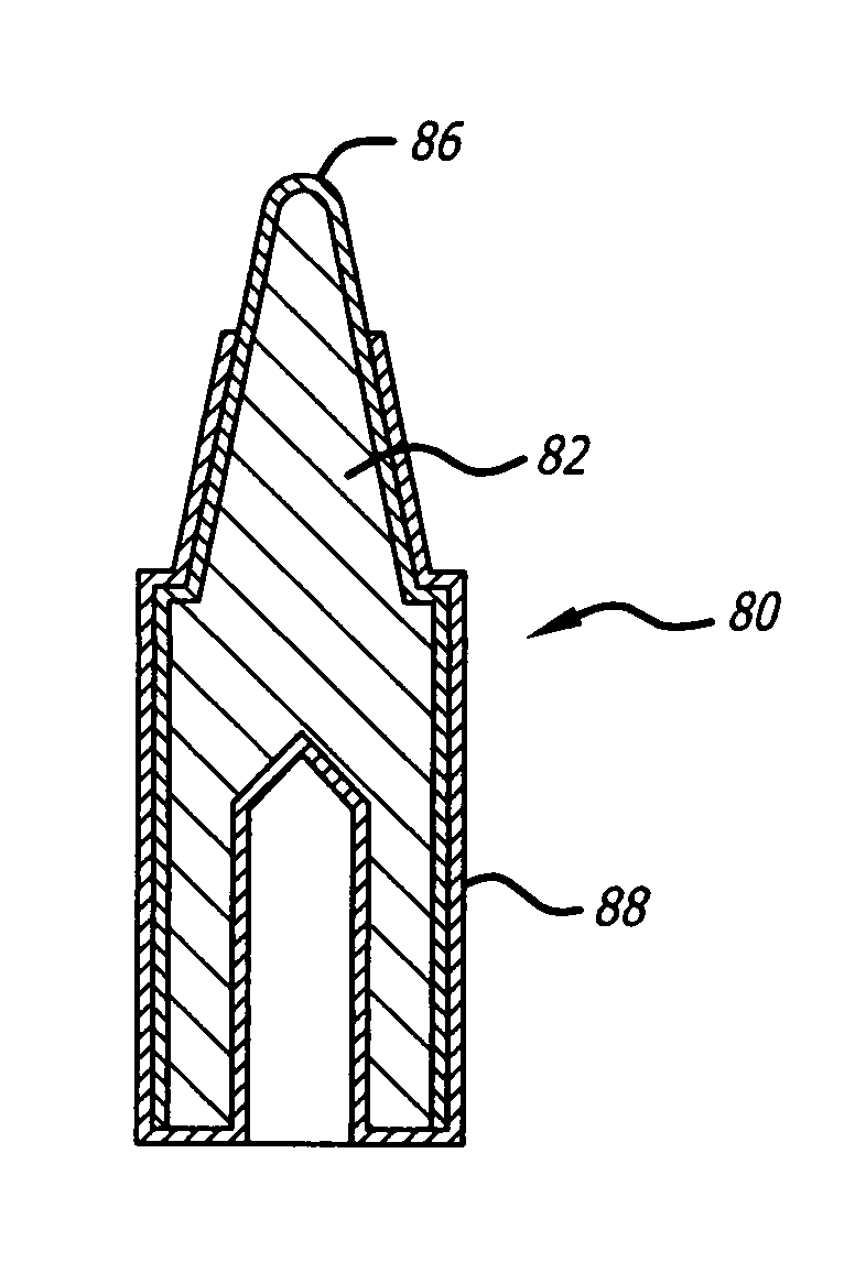
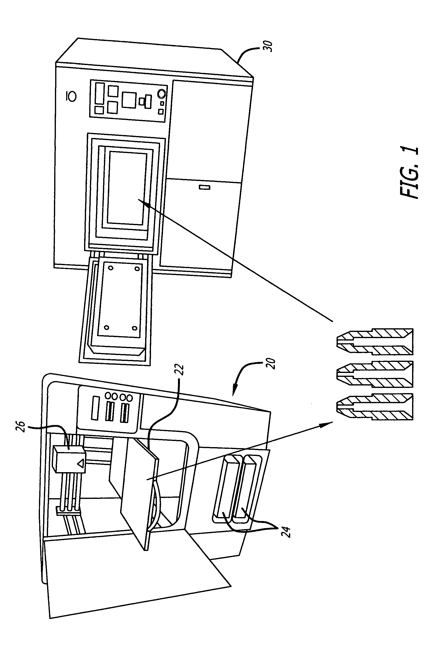
[0019]FIG. 1 depicts the steps of the process of the present invention used to formulate a powder metal article 10, in particular in the example shown a soldering tip. In the build process depicted in FIG. 1, a FDM or polymer jet 3D printer 20, provided with a computer-generated design of the three dimensional structure of an articles 10, fabricates the articles 10 in a green state by the successive deposition of layers of feedstock material on the platform 22 of the 3D printer 20. The configuration of the 3D printer 20 may be similar to the small size “uPrint” 3D printers from Stratasys based in Eden Prairie, Minn., “MakerBot Replicator” 3D printer from MakerBot Industries, LLC of Brooklyn, N.Y., or the “Cube” 3D printer from 3D Systems Corporation of Rock Hills, S.C., or the large size 3D Printers such as the “Dimension Elite” from Stratasys.

[0020]The powder metal-plastic binder material may be provided to the 3D printer in a solid or semi-solid state depending on the type of feed...


PUM

PropertyMeasurementUnit
Grain sizeaaaaaaaaaa
Temperatureaaaaaaaaaa

Abstract

A process and materials are disclosed to enable the formation of metal powder-polymer/plastic preform articles by three dimensional printing a green state article, debinding the polymer/plastic from the metal powder, and sintering the article to a final shape.

Description

BACKGROUND OF THE INVENTION[0001]In many fields it is beneficial for companies to be able to rapidly form prototypes and samples of products for customer presentations. To address this need companies have developed rapid prototyping techniques to produce prototype articles and small quantities of semi-functional or even functional parts from computer-generated design data using either a selective laser sintering process or a three-dimensional printing process. These techniques are similar to the extent that they both use layering techniques to build three-dimensional articles. Both methods form successive thin cross-sections of the desired article. The individual cross-sections are formed by bonding together adjacent grains of a granular material on a generally planar surface or a bed of the granular material. Each layer is bonded to a previously formed layer to form the desired three-dimensional article at the same time as the grains of each layer are bonded together. The process m...

Claims


Application Information

Patent Timeline
IPC IPC(8): B22F3/10B23K3/06B23K3/02B22F5/10B22F7/02
CPCB22F3/10B22F5/10B22F2005/002B23K3/025B23K3/0607B22F7/02B22F2201/10B22F2998/10Y02P10/25B22F10/18
Inventor UETANI, TAKASHISTUBER, CHRIS
Owner AMERICAN HAKKO PRODS
Why Eureka
Try Eureka