
Fuel Burning System and Method

a fuel burner and fuel technology, applied in the direction of burners, combustion regulation, combustion types, etc., can solve the problems of slow heat delivery efficiency, limited rate of volatile chemical delivery, slow melting rate of wax around the wick and creating melt pools, etc., to achieve the effect of increasing oxygen delivery

Inactive Publication Date: 2015-05-07
MASTERSON ENTERPRISES
View PDF3 Cites 1 Cited by
  • Summary
  • Abstract
  • Description
  • Claims
  • Application Information

AI Technical Summary

Benefits of technology

The patent describes a burn chamber system, a fuel burning system, and a method for delivering oxygen to the system. The system includes a wick and a wick sheath with a side wall having one or more wick sheath apertures. The wick sheath is located over the wick and has small openings that allow air to flow into the chamber and help deliver oxygen to the system. The method involves igniting a flame on the wick and supplying oxygen into the chamber through the wick sheath openings. The technical effect of this invention is to improve the delivery of oxygen to the fuel burning system and facilitate the formation of a stable flame.

Problems solved by technology

The process delivers heat slowly and inefficiently resulting in a slow rate of melting the wax around the wick and creating the melt pool.
At the same time, because the flame size is limited and the resulting heat flux generated by the flame so small, the operating temperature of a candle melt pool is barely above the melt temperature of the wax, which limits the rate and the completeness of the volatile chemical delivery and limits the pallet of active ingredients that can be functional to those that work at lower temperatures.
Because of the small flame, slow melt pool development, and low operating temperature of the melt pool, performance candles suffer from sluggish and incomplete delivery.
Performance candle formulators (like perfumers) are restricted to a limited breadth of ingredients that can be effectively used.
Further, traditional candles have flame sizes that are greatly limited.
Candles used indoors are limited in size and in heat of the flame due to the creation of soot as the candle / wick system increases in size.
As such products move outdoors, where soot can be accommodated, larger flames become increasingly difficult to create because larger wicks become difficult to ignite.
This is due to the overall mass and heat capacity of the wick and wax, which makes it difficult or impossible to vaporize the fuel for ignition.
Indoor or traditional candle type products are therefore limited in flame size and heat delivery.
Unfortunately, the flame size and heat limitations of the traditional wick and wax systems result in products that create low light and take exceptionally long times for the melt pool to develop.
In the outdoor use environment, this melt pool issue is exacerbated because of cooler air temperatures or the cooling effects of breezes.
Mineral oil type fuels, like those used in yard torches, are acutely toxic to the respiratory system upon even the slightest ingestion.
In addition, the liquid fuels are prone to creating excessive soot and develop and deliver an oil refinery off odor.
Still Further, wicks or wick material often function as a filter and, like filters, are prone to fouling or clogging resulting from prolonged use or use with “dirty” filtrate (or fuel in the case of wicks).
Most wicks are consumable and are not plagued by fouling or clogging; yet the phenomenon presents itself and can be dangerous as carbon pills form at the end of consumable wicks.
However, reusable wicks are prone to clogging or fouling by the fuel used—especially fuels that contain higher levels of longer chain hydrocarbons (products like waxes or paraffin).
These kinds of fuel with repeated use can lead to build-up of varnish, tar, carbon deposits, and other materials that can prevent the liquid fuel from flowing through the wick material, which results in diminished performance (smaller flames) and ultimately complete failure.
In effect, the chemical nature of hydrocarbon fuels and their natural inclusion of longer chain components (even at very low levels) has heretofore made using permanent or reusable wicks difficult or practically impossible.
The present inventor has recognized that an imbalance of both the priming and stoking stages of the developing flame can result in starving the flame or in partially or completely flooding the first ignition.

Method used


Image

  • Fuel Burning System and Method
  • Fuel Burning System and Method
  • Fuel Burning System and Method

Examples


Embodiment Construction

[0069]While this invention is susceptible of embodiment in many different forms, there are shown in the drawings, and will be described herein in detail, specific embodiments thereof with the understanding that the present disclosure is to be considered as an exemplification of the principles of the invention and is not intended to limit the invention to the specific embodiments illustrated.

[0070]System Overview.

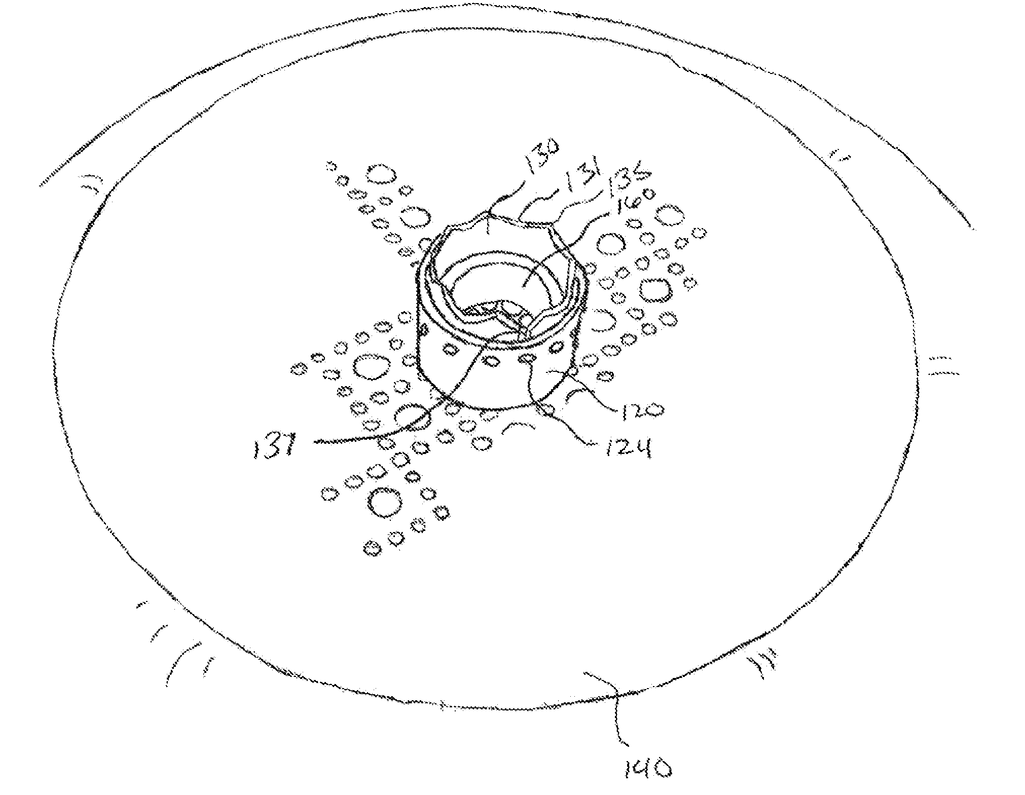
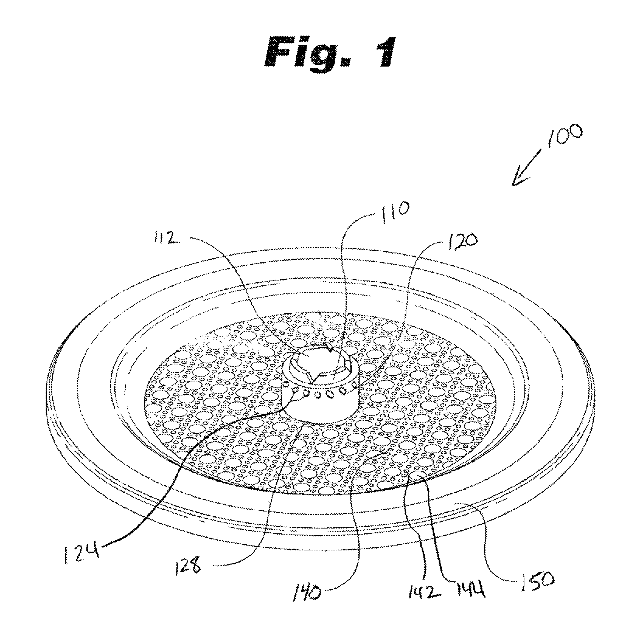
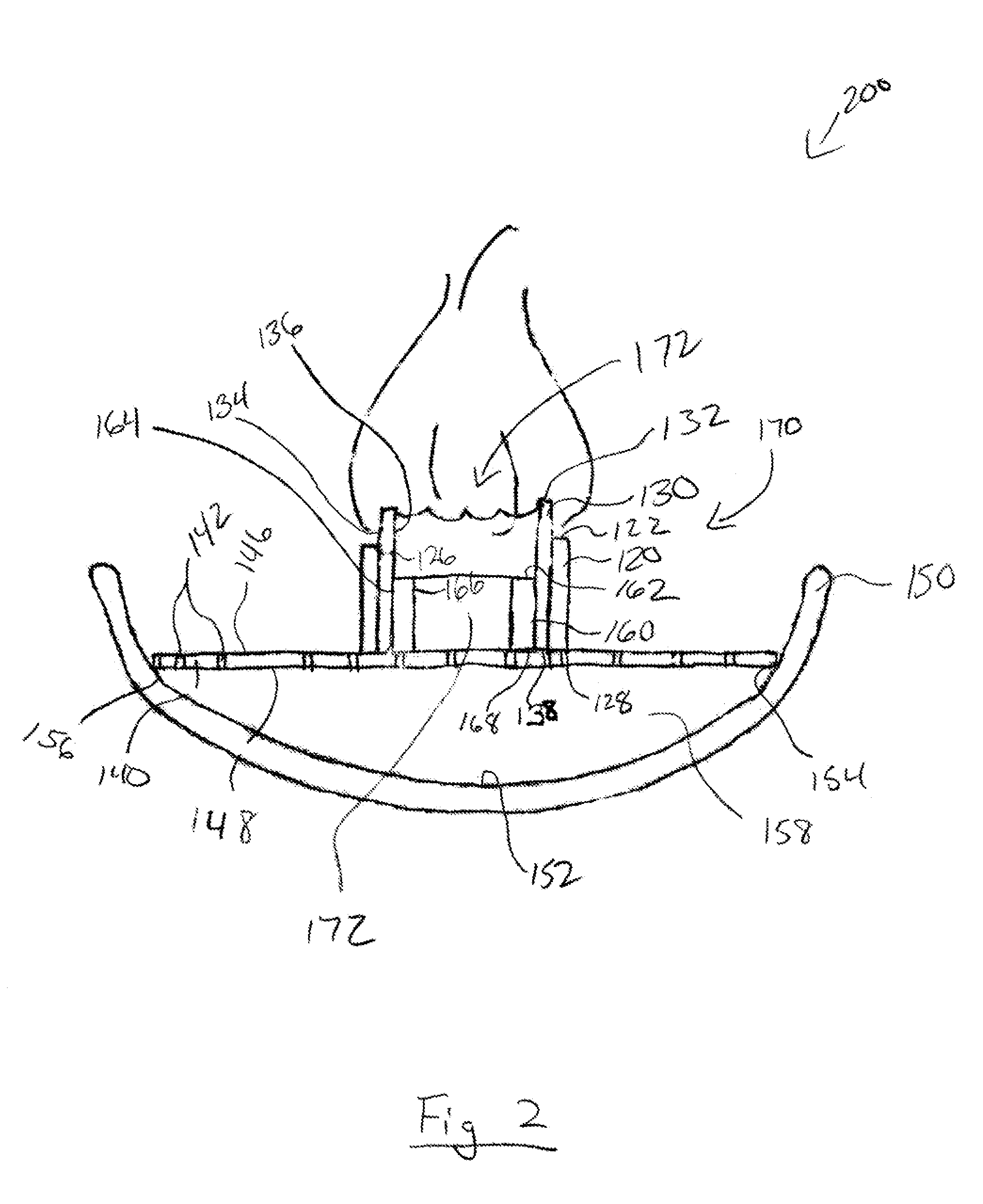
[0071]FIG. 1 shows an embodiment of a solid fuel burner system 100. The burner system 100 comprises a hollow-core wick 110, a burn chamber 112, a wick sheath 120, a melting grate 140, and a fuel reservoir 150, such as a bowl or basin. FIGS. 2-3 show an embodiment of the burner system 100 of FIG. 1 with an alternative embodiment hollow-core wick 130 and an inner wick support ring 160. The hollow-core wick 130 of FIGS. 2-3 is substituted for the hollow-core wick 110 of FIG. 1.

[0072]In general operation, a solid fuel, such as solid fuel 201, is placed on the melting grate. The ...


PUM


Abstract

A burn chamber system and a fuel burning system and method are provided. The fuel burning system has a melted fuel reservoir, a solid fuel, a melting grate configured to support the solid fuel, the melting grate located above at least a portion of the melted fuel reservoir so that at least some fuel melted on the melting grate can be received into the melted fuel reservoir. The system has at least one wick having an at least partially hollow core forming a burn chamber extending above the melting grate. A wick sheath surrounding the wick. The wick sheath has a side wall having one or more wick sheath apertures in communication with the wick.

Description

[0001]This application is a continuation of U.S. patent application Ser. No. 13 / 868,966, filed Apr. 23, 2013, which claimed the benefit of U.S. Patent Application No. 61 / 687,368, filed on Apr. 25, 2012, and U.S. Patent Application No. 61 / 687,248, filed on Apr. 23, 2012, and U.S. Patent Application No. 61 / 687,352, filed on Apr. 24, 2012, and U.S. Patent Application No. 61 / 688,750, filed on May 22, 2012, each application above is incorporated herein by reference in its entirety.FIELD OF THE INVENTION[0002]The invention relates to fuel burners and more specifically systems for burning solid fuels.BACKGROUND OF THE INVENTION[0003]Typically wax is used as a fuel in traditional candles. Traditional candles transfer heat to melt the wax around a wick via radiation. The process delivers heat slowly and inefficiently resulting in a slow rate of melting the wax around the wick and creating the melt pool. Performance candles, candles that are used to drive a volatile active ingredient into the...

Claims


Application Information

Patent Timeline
Patent Type & Authority Applications(United States)
IPC IPC(8): F23D3/08F23D5/04
CPCF23D5/04F23D3/08
Inventor MASTERSON, DANIEL J.
Owner MASTERSON ENTERPRISES
Learn More