Method for producing a rotor and electric machine having a rotor

Active Publication Date: 2015-05-21
BROSE FAHRZEUGTEILE GMBH & CO KG
View PDF11 Cites 0 Cited by
  • Summary
  • Abstract
  • Description
  • Claims
  • Application Information

AI Technical Summary

Benefits of technology

[0008]The invention is accordingly based on a first object of specifying a method for producing a rotor, which method allows magnet bodies to be securely axially fixed in the receiving pockets of a rotor with production co

Problems solved by technology

This is undesired since, as a result, the performance of the motor is reduced or it may no longer be possible to ensure i

Method used


Image

  • Method for producing a rotor and electric machine having a rotor
  • Method for producing a rotor and electric machine having a rotor

Examples


Embodiment Construction

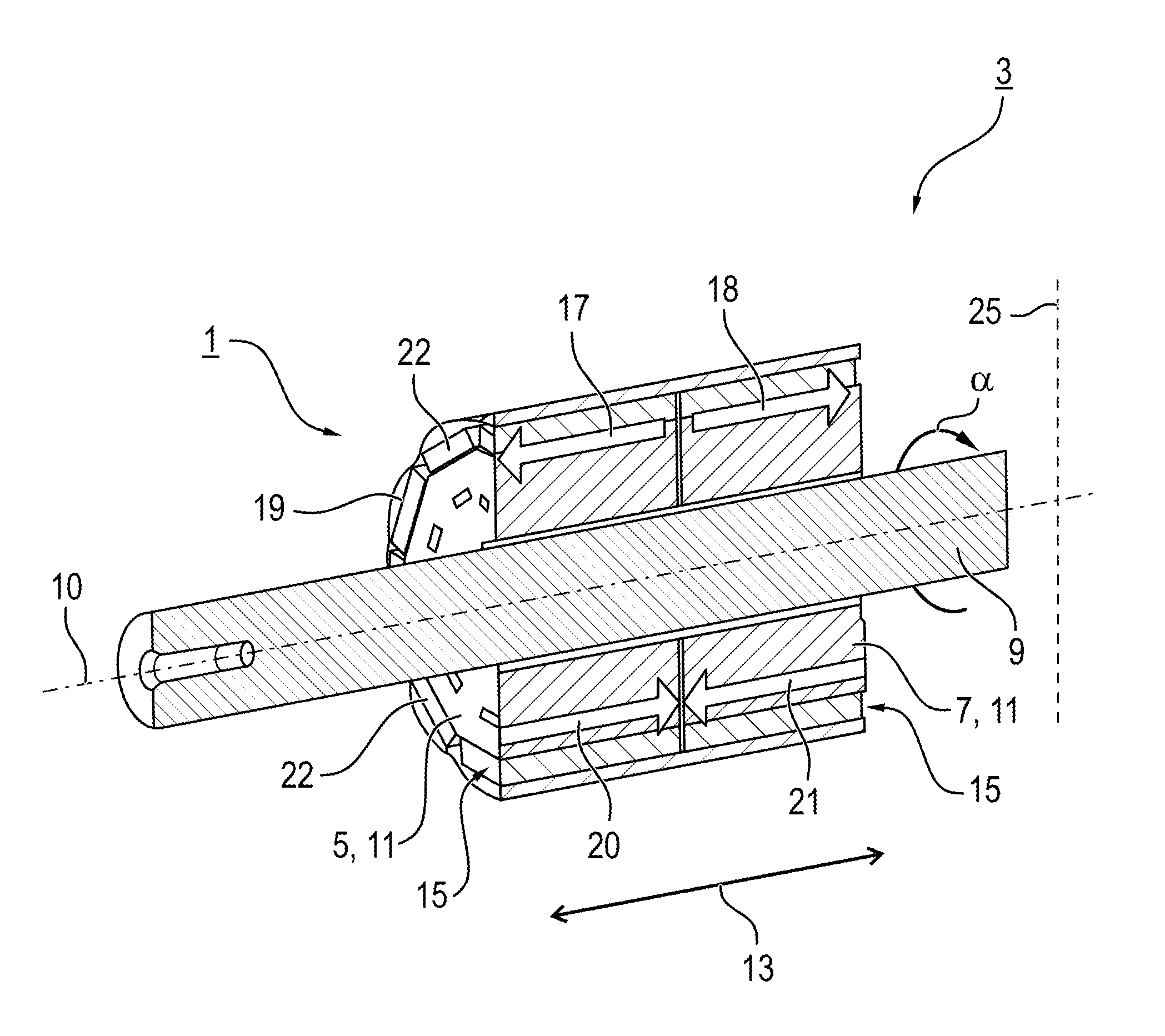
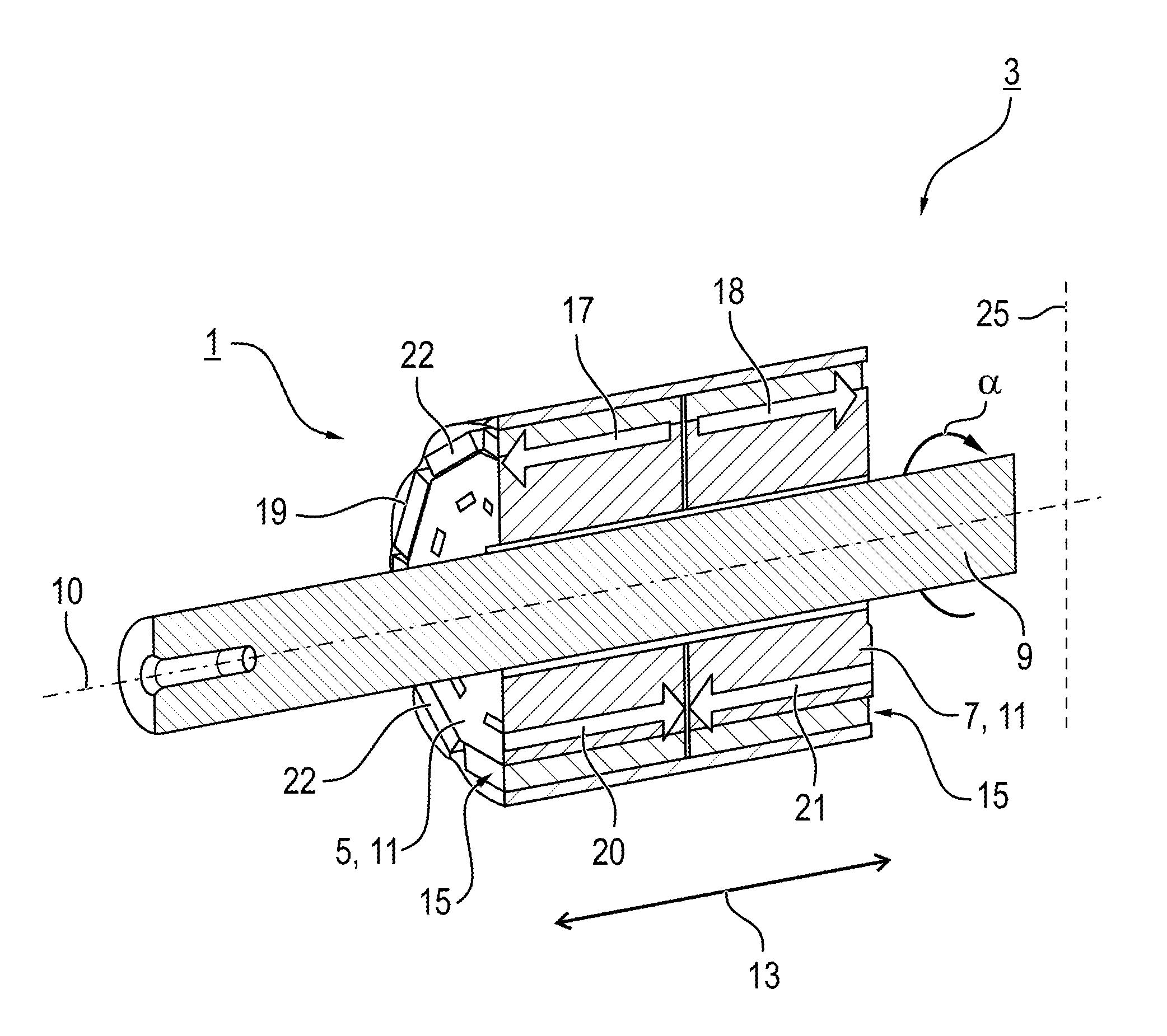
[0032]Referring now to the single FIGURE of the drawing in detail, there is shown a rotor 1 as part of an electrical machine 3 containing two rotor body elements 5, 7 which are connected to one another. The rotor 1 is arranged in a rotationally fixed manner on a shaft 9 and, in the installed state, is arranged such that it can rotate about a rotation axis 10 coaxially in relation to a stator, not illustrated. The rotor body elements 5, 7 are produced, as laminated cores, from a plurality of individual sheet metal layers 11. The sheet metal layers 11 have not been individually illustrated in order to improve clarity.

[0033]The two rotor body elements 5, 7 contain a number of receiving pockets 15 which are made in an axial direction 13. The receiving pockets 15 are made during production of the individual sheet metal layers 11 by openings being punched into each individual sheet metal layer 11 in the axial direction 13. After the sheet metal layers 11 are connected, the axial receiving...


PUM

PropertyMeasurementUnit
Angleaaaaaaaaaa
Circumferenceaaaaaaaaaa

Abstract

A method produces a rotor which can rotate about a rotation axis, in particular for an electrical machine of a motor vehicle. At least two rotor body elements are each provided with a number of receiving pockets which are made in an axial direction. Magnet bodies are in each case pressed into the receiving pockets in the rotor body elements with an axial press-in direction. The rotor body elements are joined to one another in such a way that the press-in directions of the magnet bodies point away from one another. Additionally, an electrical machine has a rotor which is produced in this manner.

Description

CROSS-REFERENCE TO RELATED APPLICATION[0001]This application claims the priority, under 35 U.S.C. §119, of German application DE 10 2013 019 318.4, filed Nov. 20, 2013; the prior application is herewith incorporated by reference in its entirety.BACKGROUND OF THE INVENTION[0002]1. Field of the Invention[0003]The invention relates to a method for producing a rotor, in particular for an electrical machine of a motor vehicle, and also to an electrical machine having a rotor.[0004]Electric motors are used in various ways in a modern motor vehicle in order to drive different actuating elements. Electric motors are used, for example, as window winder drives, sliding roof drives or seat adjustment drives, as steering system drives, as radiator fan drives or as transmission actuators. Suitable electric motors generally have to provide a large torque at high power and, in particular, be ready to operate even at high and at low temperatures.[0005]An electric motor usually has a stator which is...

Claims


Application Information

Patent Timeline
IPC IPC(8): H02K1/27H02K15/03
CPCH02K15/03H02K1/276H02K16/02Y10T29/49012H02K15/02
Inventor KURBEGOVIC-ZRNIC, JASMINSCHUMPA, CHRISTIAN
Owner BROSE FAHRZEUGTEILE GMBH & CO KG
Why Eureka
Try Eureka