Circuit delay monitoring apparatus and method

Active Publication Date: 2015-05-21
ARM LTD
View PDF2 Cites 28 Cited by
  • Summary
  • Abstract
  • Description
  • Claims
  • Application Information

AI Technical Summary

Benefits of technology

[0045]The manner in which the sampling points are distributed around the ring oscillator can be varied dependent upon embodiment, but in one embodiment the sampling points are regularly distributed around the ring oscillator. The number of sampling points provided can be varied dependent on embodiment, but in one embodiment the plurality of sampling points comprise a sampling point between each delay element, such that the plurality of delay elements comprise N delay elements. This provides the finest level of sampling, by in principal allowing the current location of the signal transition to be determined to the nearest delay element, give or take any small inaccuracies introduced

Problems solved by technology

While such techniques can give accurate results, it is becoming increasingly challenging to incorporate such analog or mixed signal circuits as the process geometry of microprocessors and SoC products decreases.
As process geometries shrink, it is also becoming more and more common to reduce the supply voltages used, and this reduction in supply voltages is one factor contributing to the difficulties in using traditional analog and mixed signal circuits to perform circuit delay monitoring.
The benefit of the approach of FIG. 2 is that it has a large dynamic range, limited by the number of stages in the edge counter but the resolution is typically poor due to limitations in the maximum frequency of the counter.
However, this still implies that glitches of magnitude N can a

Method used


Image

  • Circuit delay monitoring apparatus and method
  • Circuit delay monitoring apparatus and method
  • Circuit delay monitoring apparatus and method

Examples


Embodiment Construction

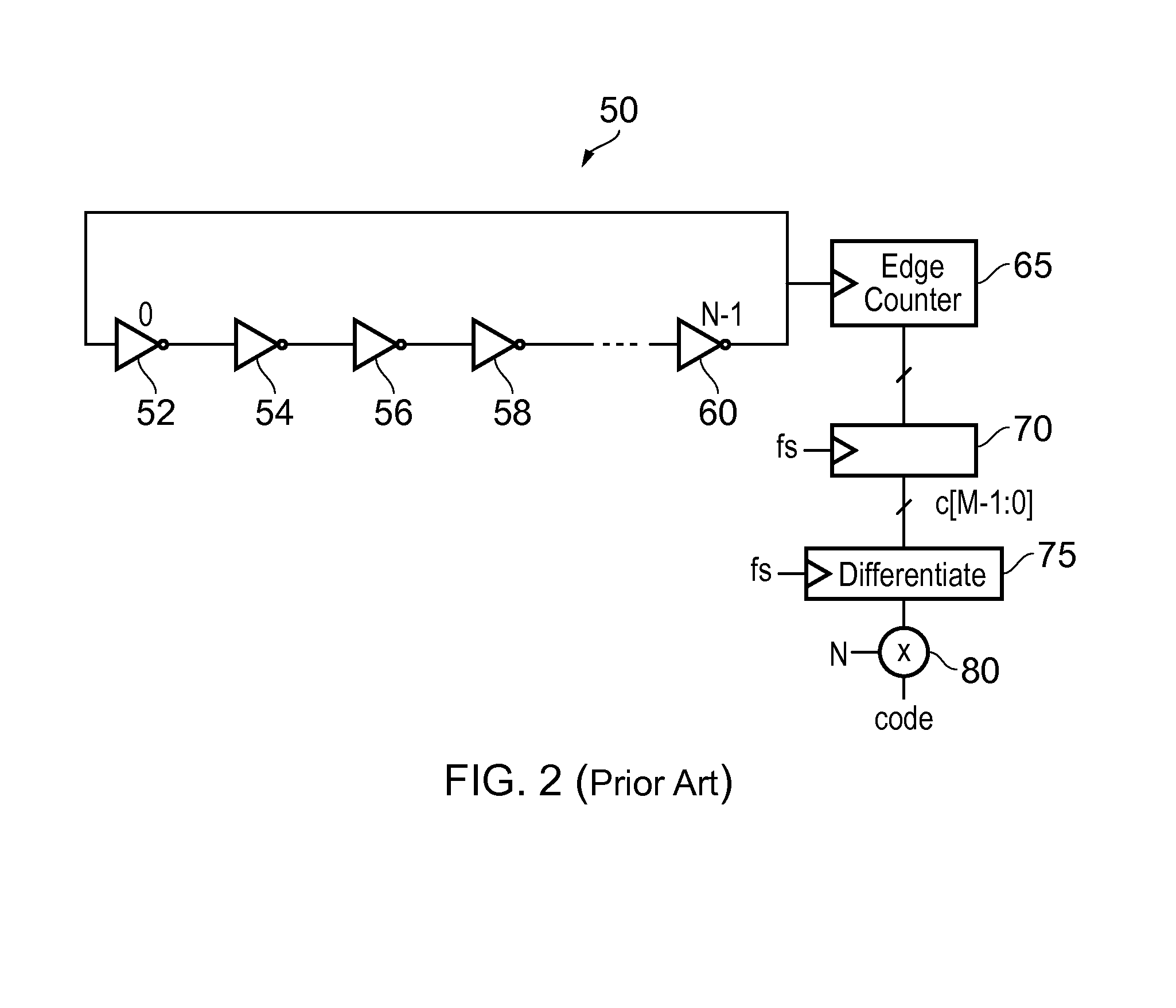
[0058]FIG. 3A illustrates a timing issue that can arise when using an edge counter 65 connected to a ring oscillator, depending on the relationship between the time at which the signal transition passes the associated location at which the edge counter 65 is connected into the ring oscillator and the timing at which the sampling circuitry 70 samples the output of the edge counter 65 based on the supplied clock signal fs. The circle 100 denotes the propagation of the signal transition around the ring oscillator. The uncertainty region 102 represents a range of distance around the associated location that the edge counter 65 is connected to the ring oscillator, such that if the signal transition is within that uncertainty region 102 at the time the clock signal fs is asserted, there is a prospect that the edge counter's 65 output will be changing during the setup or hold timing window of the flip flops within the sampling circuitry 70. As a result, there is the prospect of one or more...


PUM


Abstract

A circuit delay monitoring apparatus has a ring oscillator with a plurality of delay elements, a signal transition being propagated through the delay elements of the ring oscillator, and a plurality N of sampling points being distributed around the ring oscillator. Selection circuitry selects, in dependence on the indication of the current location of the signal transition generated by the fine sampling circuitry, one of the M transition counter circuits whose associated location is greater than said predetermined amount from the current location of the signal transition. Output generation circuitry then generates a count indication for a reference time period dependent on a sampled count value of the transition counter circuit selected by the selection circuitry, the indication of the current location of the signal transition within the ring oscillator, and reference count data relating to the start of the reference time period.

Description

BACKGROUND OF THE INVENTION[0001]1. Field of the Invention[0002]The present invention relates to a circuit delay monitoring apparatus, and to a method of monitoring circuit delay.[0003]2. Description of the Prior Art[0004]There are many instances where it is desired on-chip to monitor circuit delay. For example, such a monitored circuit delay can be used to deduce a time interval, or give an indication of voltage, temperature or process variation, and is a mechanism used in a wide range of circuits within microprocessors and System-on-Chip (SoC) products, such as phase lock loop circuits (PLLs), delay lock loop circuit (DLLs), memory interface circuits, analogue to digital converters, temperature sensors, process monitors, etc.[0005]Traditionally, such circuit delay monitoring has been performed using either analog circuits or mixed signal circuits (i.e. circuits that use a mixture of analog and digital signals). While such techniques can give accurate results, it is becoming increa...

Claims


Application Information

Patent Timeline
IPC IPC(8): H03K5/135
CPCH03K5/135
Inventor WHATMOUGH, PAUL NICHOLASDAS, SHIDHARTHABULL, DAVID MICHAEL
Owner ARM LTD
Why Eureka
Try Eureka