Machine and method for powder-based additive manufacturing

a technology of additive manufacturing and machine, applied in the direction of arc welding apparatus, electron beam welding apparatus, auxillary shaping apparatus, etc., can solve the problems of length of working zone limited by the useful perimeter of the roll, size and considerable cost of feed tray, and the need for machine complexity

Active Publication Date: 2015-05-21
MICHELIN & CO CIE GEN DES ESTAB MICHELIN
View PDF5 Cites 146 Cited by
  • Summary
  • Abstract
  • Description
  • Claims
  • Application Information

AI Technical Summary

Benefits of technology

[0016]metering means that are able to control the quantity of pow

Problems solved by technology

One disadvantage of this configuration is the size and the considerable cost of the feed tray.
Another disadvantage is derived from the fact that the length of the working zone is limited by the useful perimeter of the roll.
One disadvantage of this configuration is the size and the considerable cost of the feed tray and also the necessary complexity of the machine on account of the large number of tools to be controlled (scraper, distribution and/or compacting roll(s), rams for the trays).
One disadvantage of this configuration is the risk of a part (even a very small part) of the powder being retained on the cover and subsequently f

Method used


Image

  • Machine and method for powder-based additive manufacturing
  • Machine and method for powder-based additive manufacturing
  • Machine and method for powder-based additive manufacturing

Examples


first embodiment

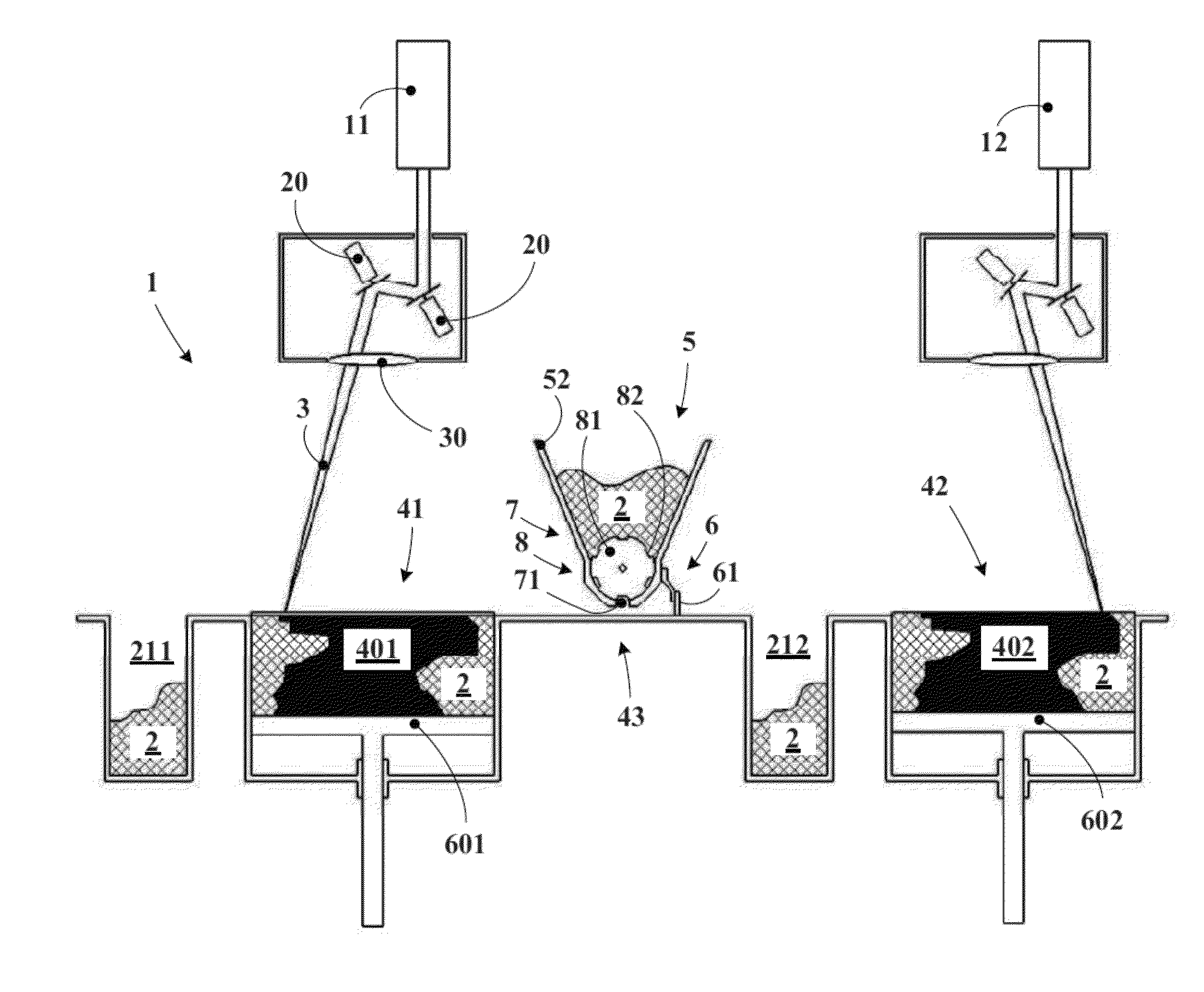
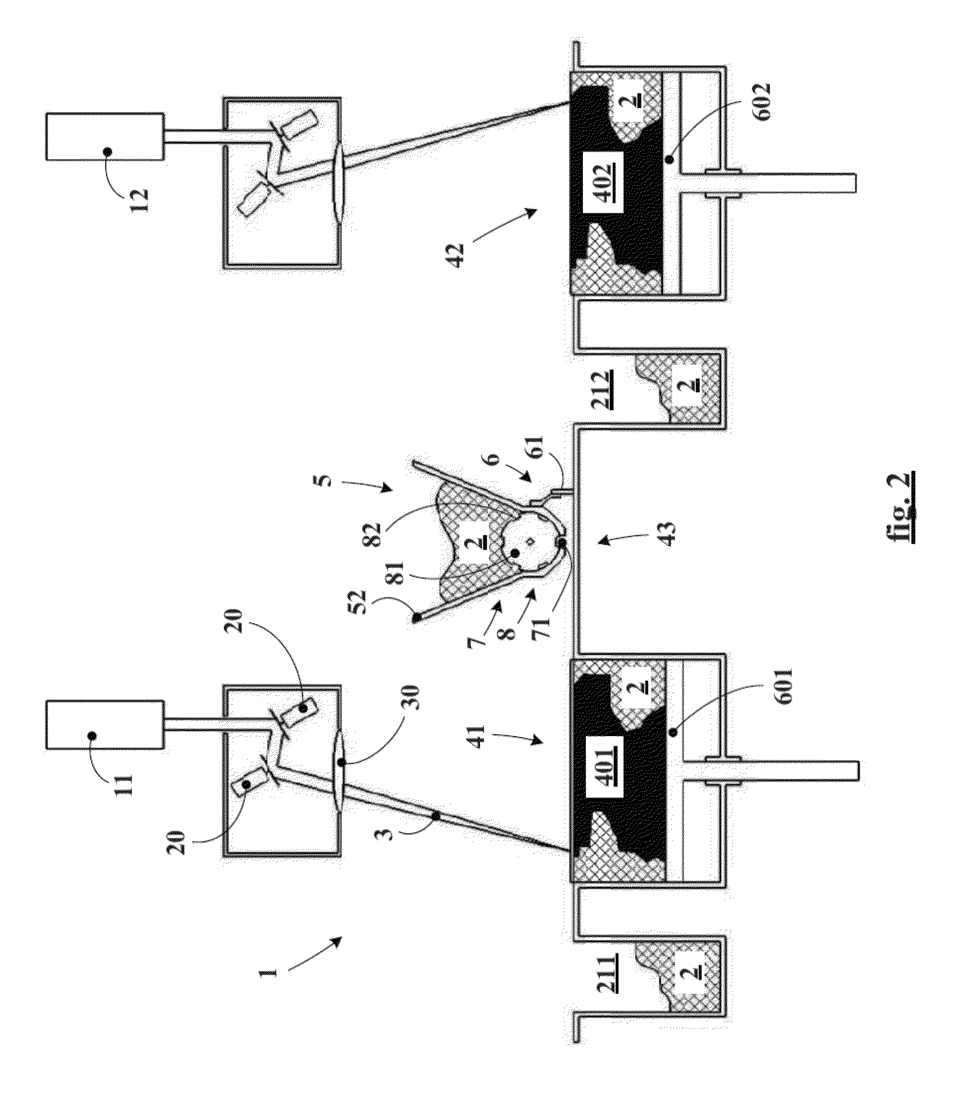
[0058]FIG. 2 shows the machine 1 according to the invention. An essential feature of the machine according to the invention is that it has two separate working zones 41 and 42 and that the layering device is common to both of these working zones. The machine thus has two separate working trays 601 and 602 that are able to move independently of one another, each of the two zones resting on its own working tray. The two working zones are coplanar. The source and the control of the energy beam are shown in a manner that is identical to FIG. 1. This is only one example of such an arrangement, however. As described in the preamble to the application, the invention is applicable in reality to all types of powder-based additive manufacturing by sintering or by completely melting the grains of said powder using an energy beam such as electromagnetic radiation (for example a laser beam) or a beam of particles (for example an electron beam). Therefore, the rest of the present description will...

second embodiment

[0073]As shown in FIG. 9, a counter-rotating compacting roller 9 may be advantageously associated with the layering device under the same conditions as those described above with reference to FIG. 7.

[0074]FIG. 10 shows a third embodiment. It differs from the first embodiment mainly in that the metering means 8 use a sliding hatch 84, the duration and amplitude of opening of which determine the quantity of powder transferred to the distributing means 6. Preferably, the storage means 5 use a flexible hopper 53 carried by a hopper support 54, so as to reduce the risk of clogging of the powder. Depending on the types of powder used, additional active unclogging means (not shown) may be employed.

third embodiment

[0075]FIG. 11 shows, on a larger scale, a variant of the third embodiment, also comprising a counter-rotating compacting roller 9, the movements of which are integral with the scraper and the hopper, as described above with reference to FIG. 7.


PUM

PropertyMeasurementUnit
Thicknessaaaaaaaaaa
Heightaaaaaaaaaa
Energyaaaaaaaaaa

Abstract

acting on a powder layer in a working zone, containing a device for layering said powder, said device including:
    • means for storing powder,
    • means for distributing powder that travel over the working zone to distribute powder in a layer having a final thickness for additive manufacturing,
    • feeding means that transfer powder from storage means to distributing means,
    • metering means that control the quantity of powder transferred from storage means to distributing means,
    • said machine being wherein:
    • storage means are positioned higher than the working zone,
    • feeding means utilize gravity,
    • feeding means and the metering means move with the distributing means,
    • the machine has two separate working zones and two separate working trays that move independently of one another,
    • each of the working trays is associated with only one working zone, and
    • the layering device is common to both working zones.

Description

[0001]This application is a 371 national phase entry of PCT / EP2013 / 061402, filed 3 Jun. 2013, which claims benefit of French Patent Application Serial No. 1255089, filed 1 Jun. 2012, the entire contents of which are incorporated herein by reference for all purposes.BACKGROUND[0002]1. Field[0003]The disclosure relates to the machines and processes for powder-based additive manufacturing by sintering or melting grains of said powder using an energy beam such as electromagnetic radiation (for example a laser beam) or a beam of particles (for example an electron beam).[0004]In particular, the disclosure relates to the architecture of the machine and to the means and processes for layering, that is to say for preparing, the bed of powder prior to sintering or to melting of said layer using the energy beam.[0005]2. Description of Related Art[0006]Document EP-1641580-B1 in particular discloses a layering device for sintering powders (metallic or ceramic) by laser. This device comprises a f...

Claims


Application Information

Patent Timeline
IPC IPC(8): B22F3/105B23K26/34B23K15/00B28B1/00
CPCB22F3/1055B28B1/001B23K26/345B33Y30/00B22F2003/1056B22F2003/1058B33Y10/00B23K15/0086B29C70/443B23K26/342B29C64/153B22F2999/00Y02P10/25B22F10/28B22F12/52B22F10/73B22F12/57B22F12/63B22F3/004
Inventor PIALOT, JR., FREDERICWALRAND, GILLESWIEL, PIERRE
Owner MICHELIN & CO CIE GEN DES ESTAB MICHELIN
Why Eureka
Try Eureka