Continuous annealing furnace for steel strip, continuous annealing method, continuous galvanizing apparatus and method for manufacturing galvanized steel strip (as amended)

a technology of continuous annealing furnace and steel strip, which is applied in the direction of furnaces, heat treatment equipment, charge manipulation, etc., can solve the problems of reducing productivity, surface appearance defects or defects in chemical conversion treatment such as phosphate treatment, and preventing productivity from being lowered. , the effect of reducing the moisture concentration

Active Publication Date: 2015-05-21
JFE STEEL CORP
View PDF2 Cites 11 Cited by
  • Summary
  • Abstract
  • Description
  • Claims
  • Application Information

AI Technical Summary

Benefits of technology

[0031]According to the present invention, it is possible to decrease the time until the dew point of the furnace atmosphere is decreased to −30° C. or lower so that manufacturing of steel strip can be stably performed by decreasing moisture concentration and/or oxygen concentration in a furnace atmosphere before performing a regular operation in which a steel strip is subjected to a continuous heat treatment or when there is an increase in moisture concentration and/or oxygen concentration in the furnace atmosphere during a regular operation, which can prevent the productivity from being lowered.
[0032]In addition, according to the present inven...

Problems solved by technology

However, in the case of such a conventional method, since it takes a long time to decrease moisture content and oxygen concentration of the furnace atmosphere to specified levels which are appropriate for a regular operation, and since the furnace cannot be operated during all that time, there is a problem in that there is a significant decrease in productivity.
However, in the case of a high-strength cold-rolled steel strip containing easily oxidized chemical elements such as Si and Mn, there is a problem in that these easily oxidized chemical elements are concentrated in the surface of the steel strip during annealing and oxides of, for example, Si and Mn are formed, which results in surface appearance defects or defects in a chemical conversion treatment such as a phosphating treatment.
In the case of a galvanized steel strip, when it contains easily oxidized chemical elements such as Si and Mn, there is a problem in that these easily oxidized chemical elements are concentrated in the surface of the steel strip during annealing and oxides of, for example, Si and Mn are formed, which results in coating defects due to a decrease in zinc coatability or results in a decrease in alloying speed at the time when an alloying treatment is performed after a plating treatment has been performed.
In particular, in the case Si, when an oxide film of SiO2 is formed on the surface of a steel strip, Si causes a significant decrease in wettability between the steel strip and molten platin...

Method used


Image

  • Continuous annealing furnace for steel strip, continuous annealing method, continuous galvanizing apparatus and method for manufacturing galvanized steel strip (as amended)
  • Continuous annealing furnace for steel strip, continuous annealing method, continuous galvanizing apparatus and method for manufacturing galvanized steel strip (as amended)
  • Continuous annealing furnace for steel strip, continuous annealing method, continuous galvanizing apparatus and method for manufacturing galvanized steel strip (as amended)

Examples


example 1

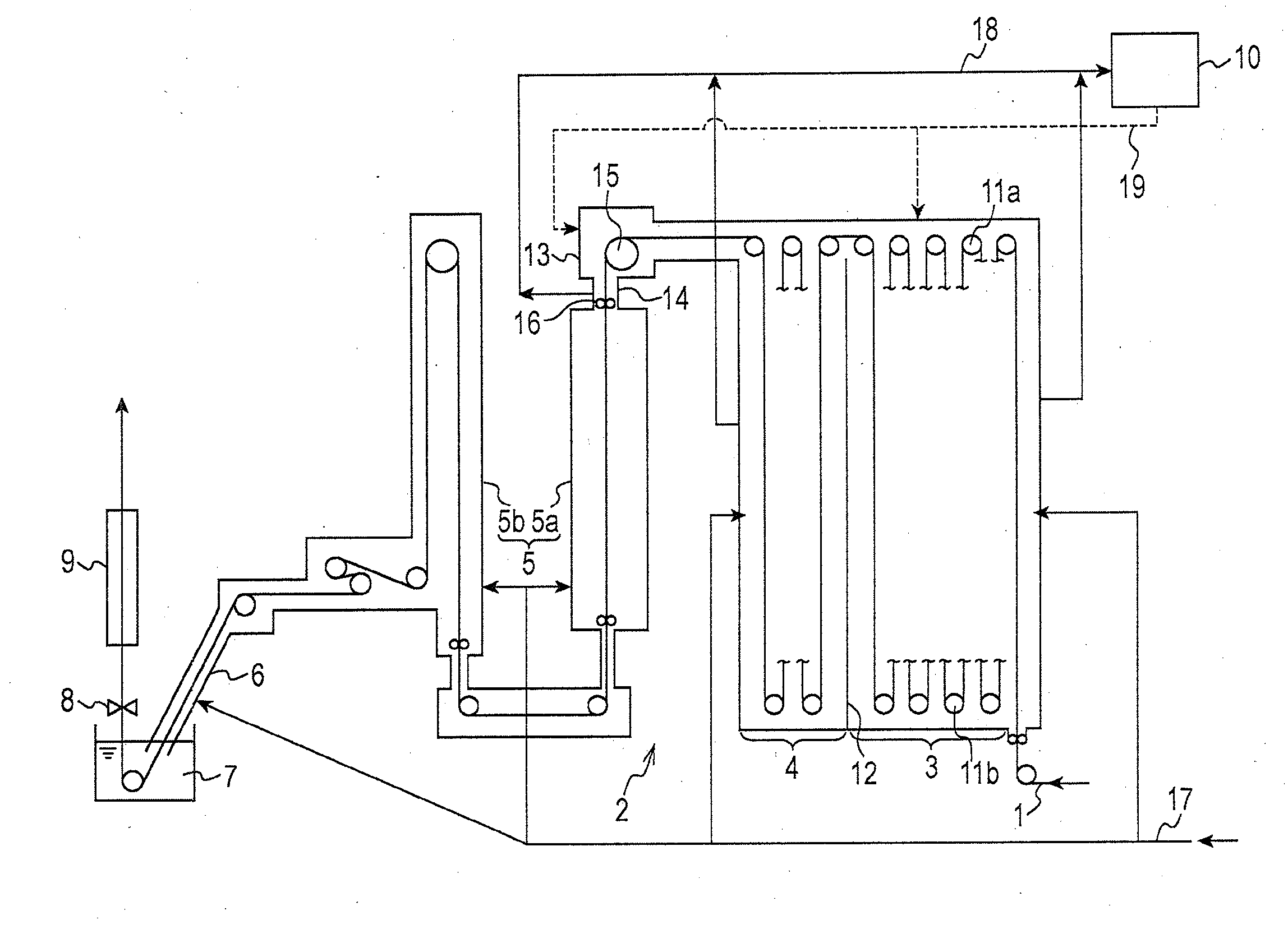
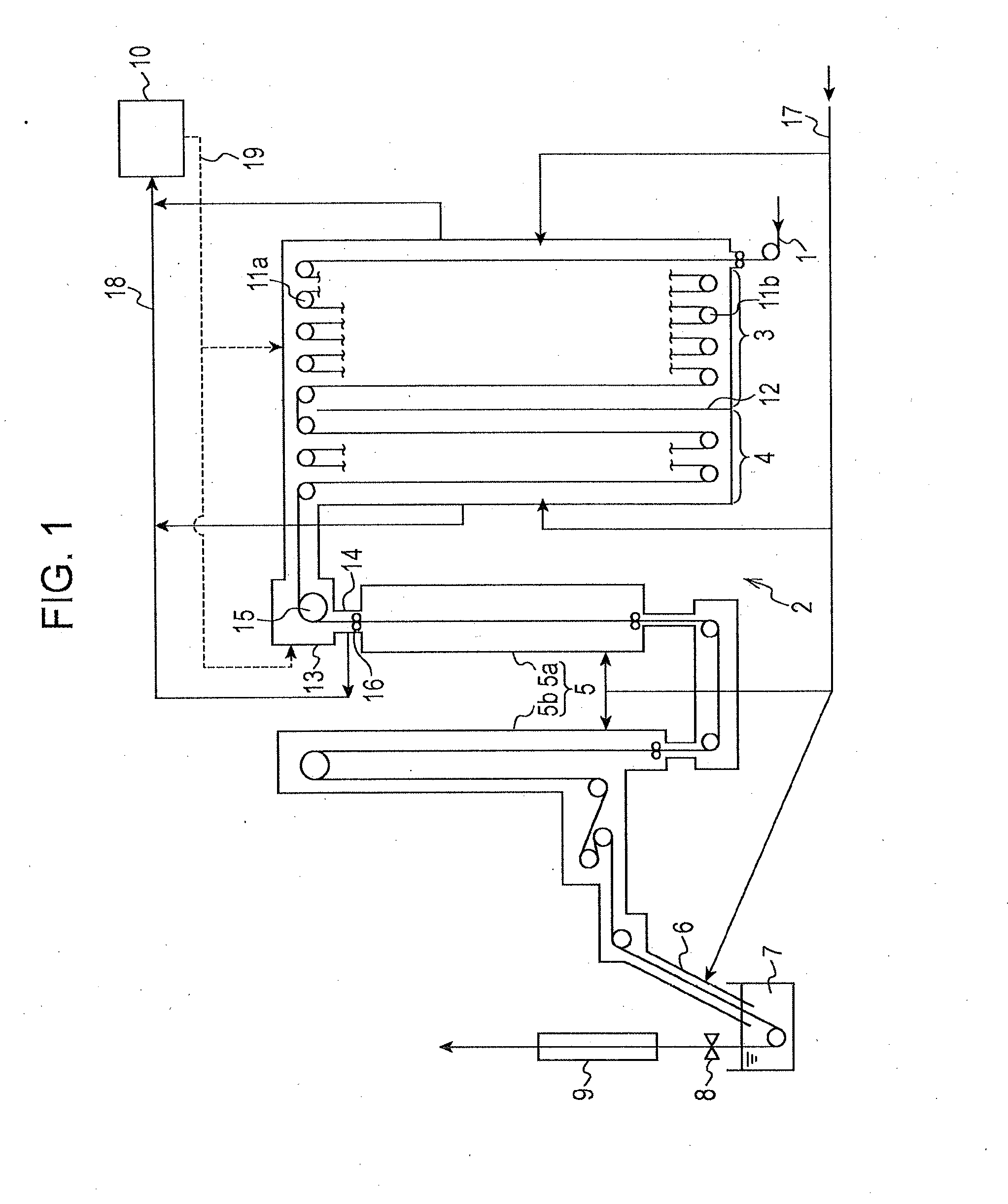
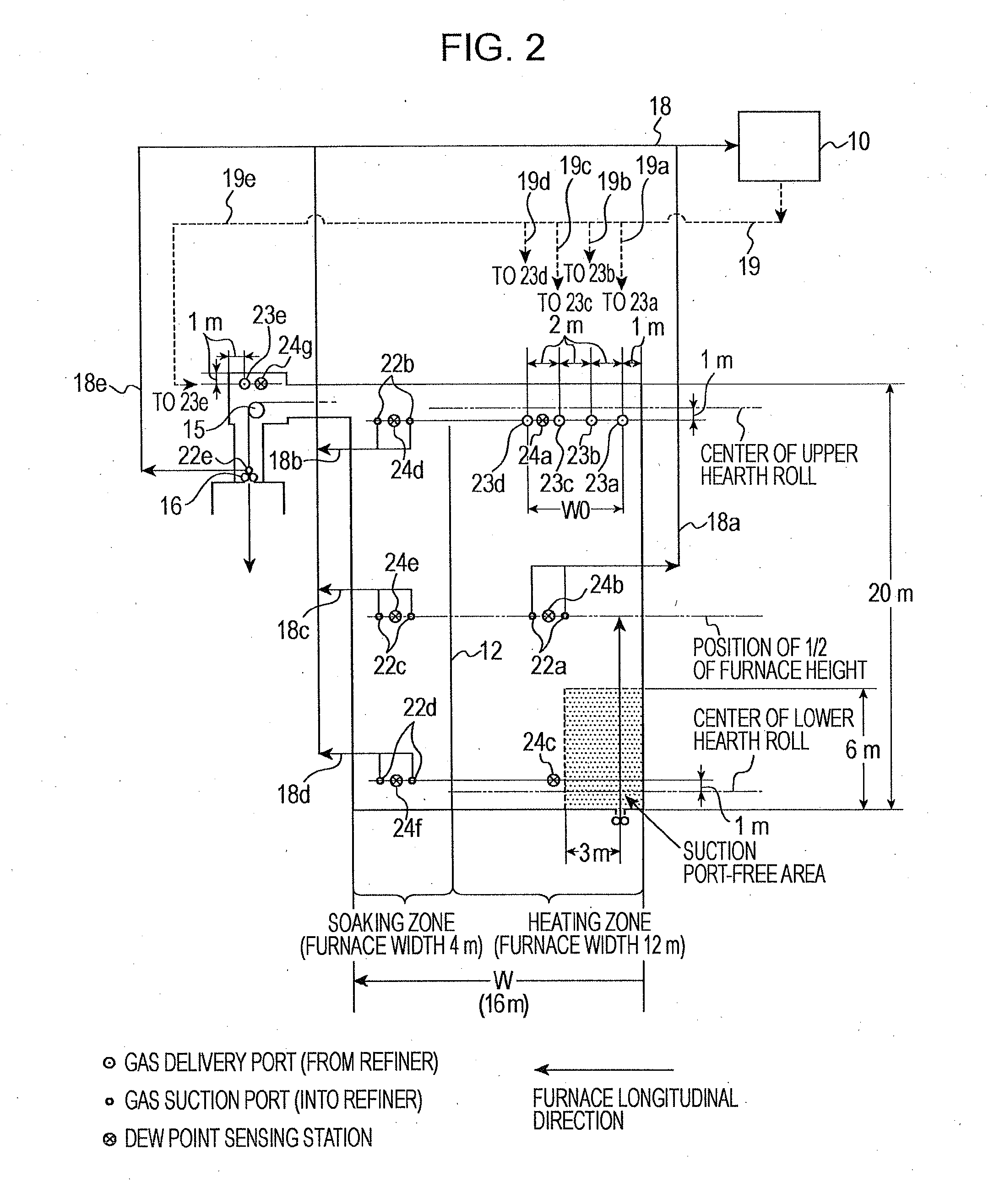
[0085]Using an ART type (all radiant type) CGL (having an annealing furnace length (total pass length of a steel strip in the annealing furnace) of 400 m and a furnace height of a heating zone and a soaking zone of 20 m) illustrated in FIG. 1, dew point determining test was performed. The furnace width (W) of the heating zone was 12 m and the furnace width of the soaking zone was 4 m, which resulted in the total furnace width of the heating zone and the soaking zone being 16 m.

[0086]Atmospheric gas feeding positions from the outside of the furnace were, in the soaking zone, located at positions 1 m and 10 m higher than the hearth on the driving side with 3 positions in a line in the longitudinal direction being located on each height, that is, 6 positions in total, and, in the heating zone, located at positions 1 m and 10 m higher than the hearth on the driving side with 8 positions in a line in the longitudinal direction being located on each height, that is, 16 positions in total....

example 2

[0102]Using the ART type (all radiant type) CGL illustrated in FIG. 1 which was used in EXAMPLE 1, the decreasing trend of the dew point was investigated.

[0103]The conditions of the conventional method (in which a refiner was not used) were as follows. That is, the atmospheric gas which was fed into the furnace consisted of H2: 8 vol % and the balance being N2 and inevitable impurities (having a dew point of −60° C.), the amount of gas fed to the cooling zone and the downstream part thereof: 300 Nm3 / hr, the amount of gas fed to the soaking zone: 100 Nm3 / hr, and the amount of gas fed to the heating zone: 450 Nm3 / hr. In addition, using a steel strip having a thickness of 0.8 to 1.2 mm and a width of 950 to 1000 mm (containing the same alloying elements as given in Table 1), an annealing temperature was 800° C., and a steel strip traveling speed was 100 to 120 mpm.

[0104]The conditions of the method according to the present invention were the same as described above, and, further, using...


PUM

PropertyMeasurementUnit
Lengthaaaaaaaaaa
Lengthaaaaaaaaaa
Widthaaaaaaaaaa

Abstract

Provided is a vertical annealing furnace, in which a heating zone and a soaking zone are communicated with each other in the upper part of the furnace, in which a part of the furnace other than the communicated parts is separated by a dividing wall, in which part of the furnace gas is suctioned into a refiner having a deoxidation device and a dehumidification device which is placed outside the furnace to decrease the dew point of the gas by removing oxygen and moisture from the gas and such that the resultant gas having a decreased dew point is returned into the furnace, in which a gas suction port into the refiner is located in the lower part of the connection part between the soaking zone and the cooling zone and in which one or more gas suction ports are located in the parts of the heating zone and/or the soaking zone outside of an area within 6 m in the vertical direction and 3 m in the longitudinal direction of the furnace from the steel strip entrance in the lower part of the heating zone.

Description

CROSS REFERENCE TO RELATED APPLICATIONS[0001]This is the U.S. National Phase application of PCT / JP2013 / 003199, filed May 20, 2013, which claims priority to Japanese Patent Application No. 2012-118116, filed May 24, 2012, the disclosures of each of these applications being incorporated herein by reference in their entireties for all purposes.FIELD OF THE INVENTION[0002]The present invention relates to a continuous annealing furnace for a steel strip, a continuous annealing method, a continuous galvanizing apparatus and a method for manufacturing a galvanized steel strip.BACKGROUND OF THE INVENTION[0003]In the past, in the case of a continuous annealing furnace for annealing a steel strip, for example, when operation is resumed after the furnace has been exposed to atmospheric air or when atmospheric air is mixed in a furnace atmosphere, a method for replacing the furnace atmosphere with a non-oxidizing gas, in which a non-oxidizing gas such as an inert gas is fed into the furnace as ...

Claims


Application Information

Patent Timeline
IPC IPC(8): C23C2/02C23C2/00
CPCC23C2/003C23C2/02C21D1/26C21D1/74C21D1/76C21D9/56C21D9/561C23C2/06C23C2/28C23C2/40F27B9/28F27D7/04C23C2/0224C23C2/0035C23C2/004C23C2/0222F27B9/045C23C2/0038B05D3/0218B05D7/14
Inventor TAKAHASHI, HIDEYUKISATO, NOBUYUKINAKAZATO, KAZUKITAKADA, MOTOKI
Owner JFE STEEL CORP
Why Eureka
Try Eureka