Method of digitally constructing a prosthesis

Active Publication Date: 2015-05-21
LAYMAN WILLIAM STRATFORD +1
View PDF18 Cites 19 Cited by
  • Summary
  • Abstract
  • Description
  • Claims
  • Application Information

AI Technical Summary

Benefits of technology

[0012]The method and process of the present invention solves the problems confronted in the art in a simple and straightforward manner. What is provided is a process for making a prosthetic limb, wherein one would retrieve a manipulated file from a computer that has been through the test socket phase; that file will be manipulated through the definitive socket phase using specific 3D prosthetic software to design the socket for current practi

Problems solved by technology

If these criteria are not achieved, when the patient uses the prosthesis, residual limb soft tissue breakdown often occurs.
The result is painful sores, blisters, ulcers, or cysts on the residual limb that typically restrict continued prosthesis use, and in severe cases, necessitate a further amputation to a higher anatomical level, which can lead to

Method used


Image

  • Method of digitally constructing a prosthesis
  • Method of digitally constructing a prosthesis
  • Method of digitally constructing a prosthesis

Examples


Embodiment Construction

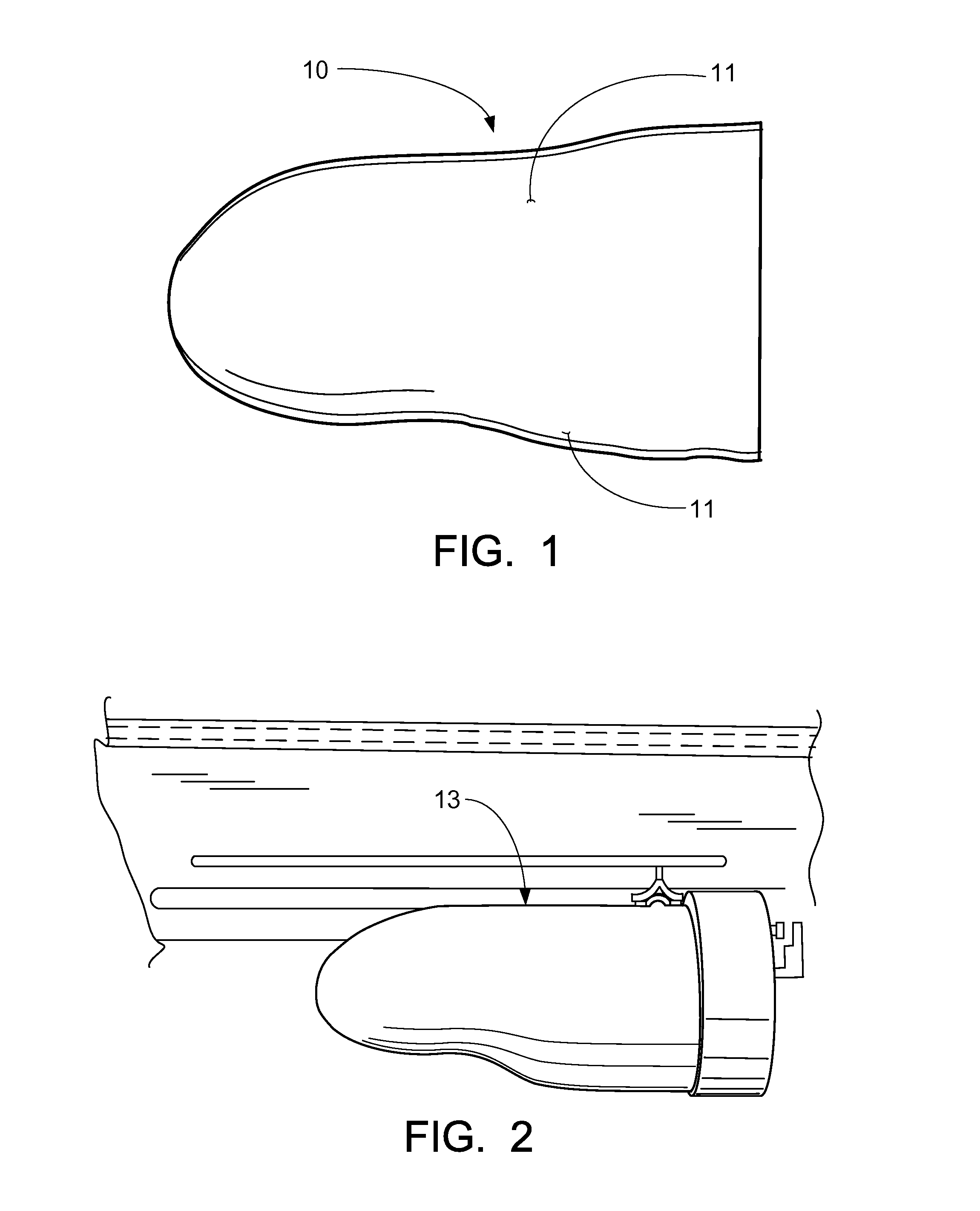
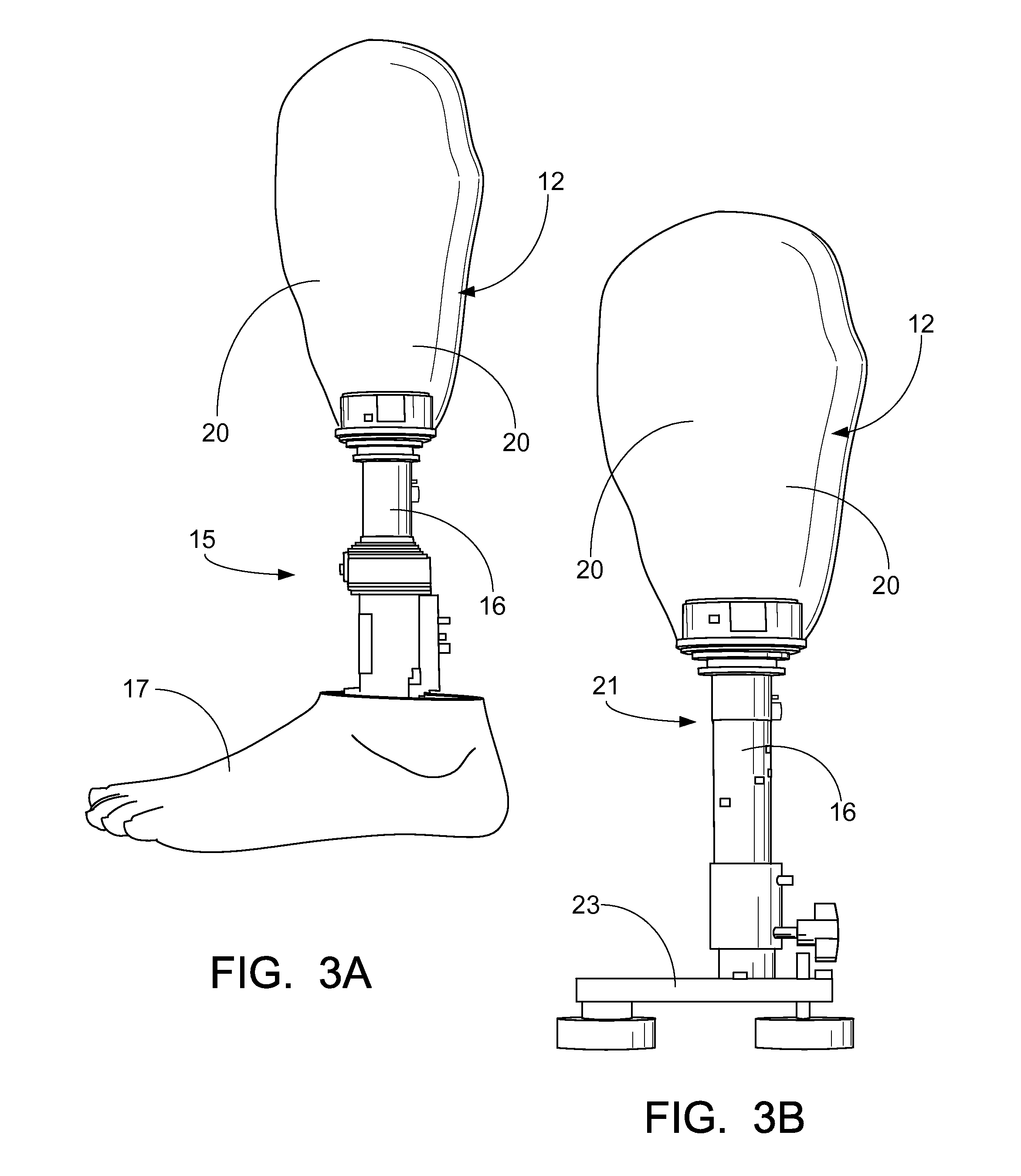
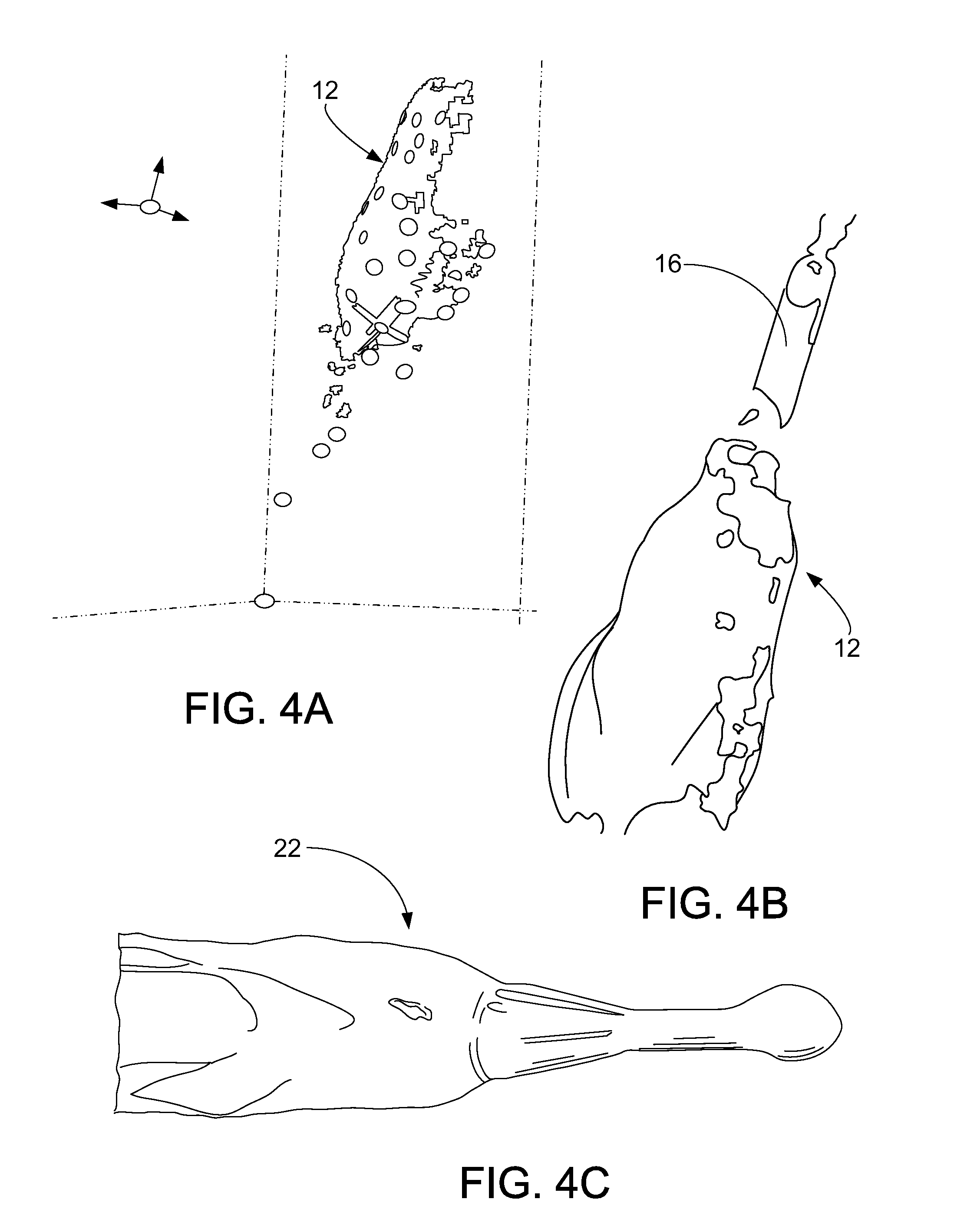
[0037]FIGS. 1 through 12 illustrate a preferred embodiment of the method or process of constructing a prosthetic limb through a digital format, while FIGS. 13 and 14 illustrate in Flow Chart format the steps of Smoothing the prosthetic limb (3D socket) and Sealing the prosthetic limb (3D socket) respectively.

[0038]Before reference is made to the Figures, in general, this technique of achieving a positive mold for a test socket in a digital format is by scanning the residual limb. The first step would be to choose the materials and tools needed for measuring a patient. Again, one would need to prepare suspension of the prosthesis (silicone liner, foam or other types of socket designs); a scanner; a laptop; reflective dots; measuring tools such as a length stick M / L gauge tape measure, etc. The method may vary by which Distal Device used.

[0039]After preparing oneself with the items one would need to take a digital image of a residual limb, the individual would use a scanner to capture...


PUM

PropertyMeasurementUnit
Strengthaaaaaaaaaa
Contentaaaaaaaaaa

Abstract

A prosthetic limb and process to digitally construct a prosthetic limb which includes first, digitally producing a modified mold of a residual limb via 3d scanners and software known to the industry; constructing a test socket from the digitally modified mold and be equipped with an alignable system; for example, a pylon, along with the desired prosthetic foot; accurately scanning the test socket, preferably with a 3D scanner, along with finalized alignment that has been recorded and adjusted by a certified practitioner to provide a 3-D Image of the finalized prosthetic alignment; transferring the finalized digital alignment of the test socket to the finalized digitally modified mold; once the modified model has received the transferred alignment, fabricating the type of hookup in the socket; i.e., plug fit, four hole, support drop lock, or any other type of industry standard connection or accommodation via basic 3D software; and once the desired prosthetic attachment is finalized, the next step is to send the finished file to a 3-D printer to produce the definitive prosthetic device. The 3-D printed socket would then be placed in a vibratory finishing system to smooth out the interior and exterior surfaces of the printed socket; and the walls of the 3-D printed socket would be sealed by applying a mixture of epoxy sealant, for example, TC-1614, to the inside and outside walls of the socket, and placing the socket into an oven for a sufficient amount of time to seal the walls of the socket. Preferably, the prosthesis would be printed out of Nylon 12 material or of a strong plastic, such as ULTEM®, or carbon fiber, or other material of equivalent or greater strength that may be known or developed in the future.

Description

CROSS-REFERENCE TO RELATED APPLICATIONS[0001]This is a continuation-in-part of U.S. patent application Ser. No. 13 / 948,361, filed Jul. 23, 2013, which claims benefit of U.S. Provisional Patent Application Ser. No. 61 / 674,720, filed Jul. 23, 2012, each of which is hereby incorporated herein by reference, and priority of each of which is hereby claimed.STATEMENT REGARDING FEDERALLY SPONSORED RESEARCH OR DEVELOPMENT[0002]Not applicableREFERENCE TO A “MICROFICHE APPENDIX”[0003]Not applicableBACKGROUND OF THE INVENTION[0004]1. Field of the Invention[0005]The present invention relates to prosthetics. More particularly, the present invention relates to a novel process for constructing a prosthetic limb through a series of fabrication steps including retrieving a file from a computer, manipulating that file that has captured alignment and socket fit, then having to adjust each “Z” line in the file to insure the strongest build of the socket with proper trim lines, sending it to a 3D printer...

Claims


Application Information

Patent Timeline
IPC IPC(8): A61F2/50B29C67/00G06F17/50
CPCA61F2/5046A61F2002/505B29C67/0088G06F17/50A61F2002/5049B29C64/386G06F30/00
Inventor LAYMAN, W. BRIANLAYMAN, WILLIAM STRATFORD
Owner LAYMAN WILLIAM STRATFORD
Why Eureka
Try Eureka