High-temperature thermal storage device with induction heating and molten metal, and thermal storage-composite system

a thermal storage device and induction heating technology, applied in the direction of heat storage devices, indirect heat exchangers, lighting and heating apparatus, etc., can solve the problem of no longer attained temperature level, at which the storage device was charged, and loss of exergy

Inactive Publication Date: 2015-05-28
ENOLCON
View PDF7 Cites 10 Cited by
  • Summary
  • Abstract
  • Description
  • Claims
  • Application Information

AI Technical Summary

Benefits of technology

[0044]An operating mode wherein the high-temperature thermal storage device is charged with electric energy and simultaneously discharged via the steam in the tubular duct may be useful during the day, for example, when clouds are passing through, when it is nonetheless desired to have the high-temperature thermal storage device also at an appropriately high charge state at night. This means further flexibility, i.e. during the day the solar power station can even be operated when

Problems solved by technology

When storing thermal energy in the form of high temperature heat, exergy is lost during charging and discharging of the thermal energy storage device.
This exergy loss arises because the temperature level, at which the storage device was charged, is no longer attained when discharging the storage device.
As a result thereof, exergy l

Method used


Image

  • High-temperature thermal storage device with induction heating and molten metal, and thermal storage-composite system
  • High-temperature thermal storage device with induction heating and molten metal, and thermal storage-composite system
  • High-temperature thermal storage device with induction heating and molten metal, and thermal storage-composite system

Examples


Embodiment Construction

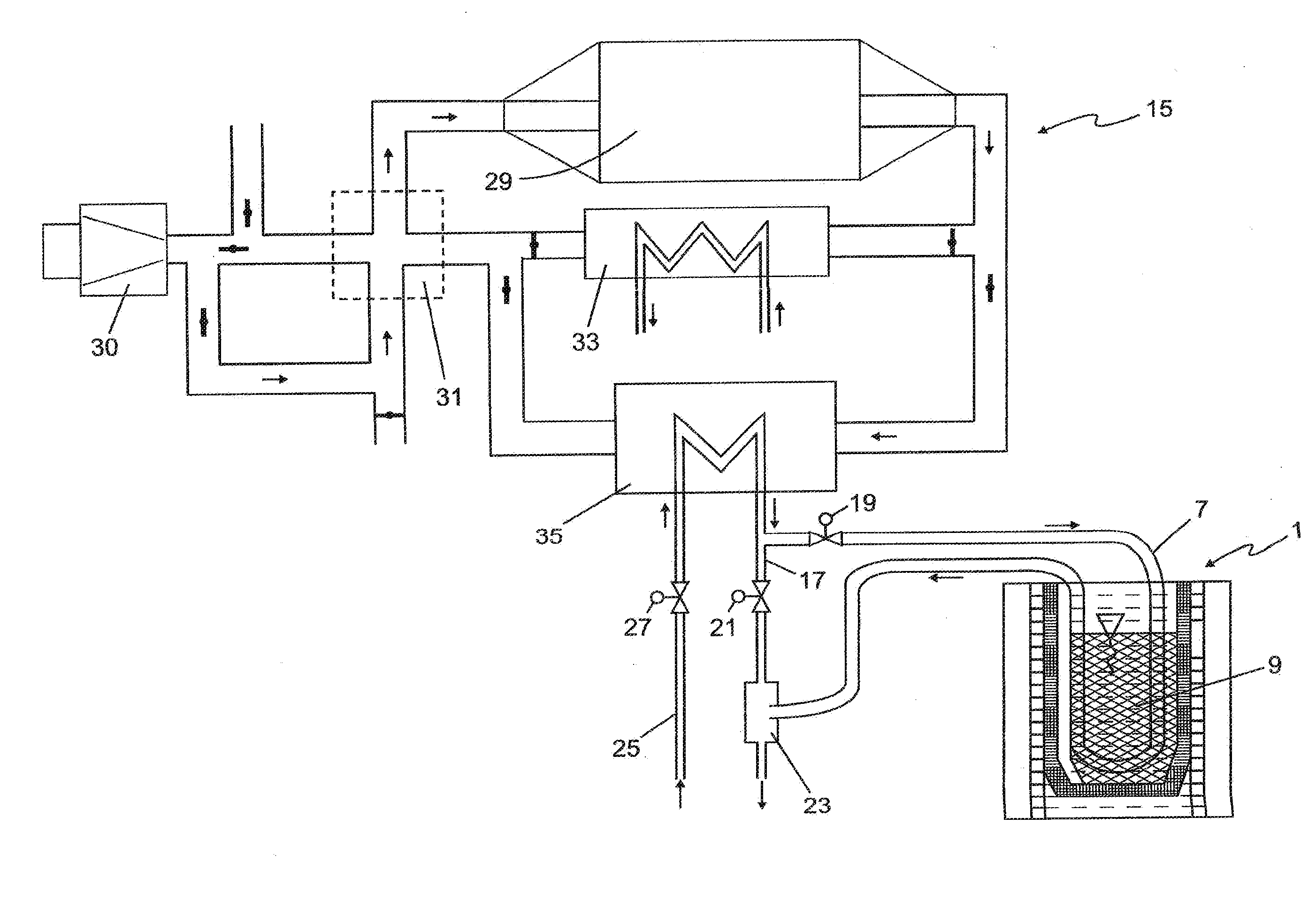
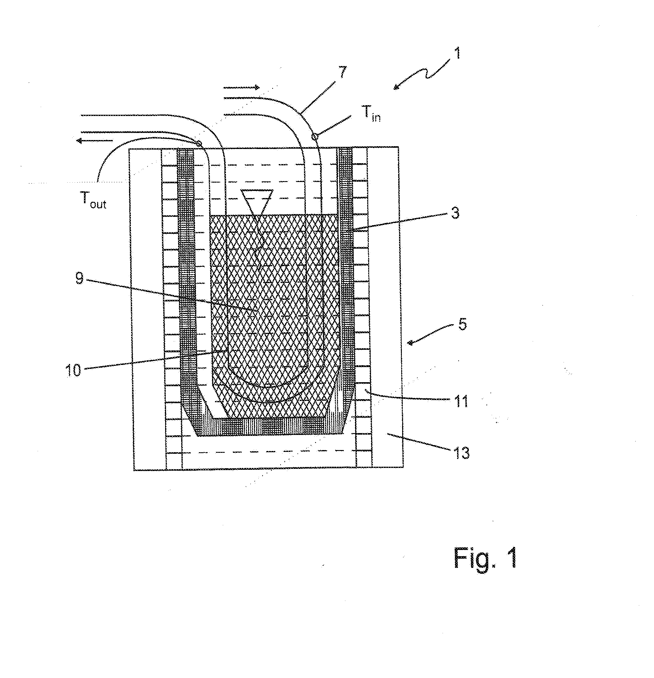
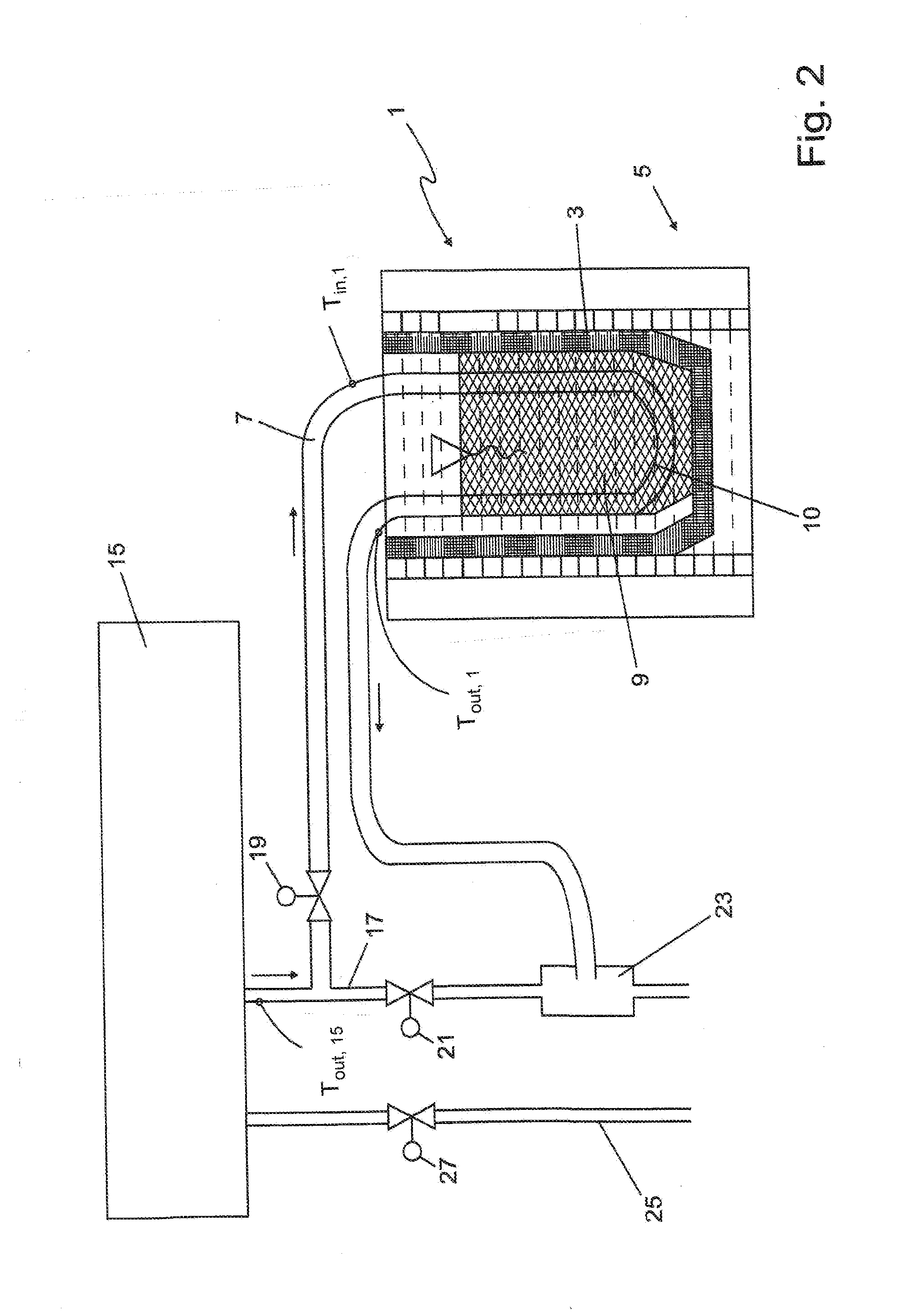
[0057]FIG. 1 shows a working example of a high-temperature thermal storage device 1 according to the invention in a highly simplified and schematic section view. The essential components of the high-temperature thermal storage device 1 according to the invention are a crucible 3, an induction heating device 5, a tubular duct 7 as well as molten metal 9 inside the crucible 3. The crucible 3 is a receptacle which is heat-resistant, even if the molten metal 9 is liquid, and, for example, has temperatures exceeding 700° C. In order to minimize heat loss, the crucible 3 includes a lid (without reference number) at its upper end.

[0058]The sidewalls of the crucible 3 are surrounded by the induction heating device 5. Such induction heating devices 5 are often used in induction furnaces and consist substantially of one or a plurality of coils 11 as well as sheet metal jacketing 13.

[0059]Since such crucibles 3 and induction heating devices 5 are known from induction furnaces for foundries, th...


PUM

PropertyMeasurementUnit
Temperatureaaaaaaaaaa
Melting pointaaaaaaaaaa
Temperatureaaaaaaaaaa

Abstract

A high-temperature thermal storage device has a crucible, an induction heating device, a tubular duct in which a liquid and/or gaseous heat carrier flows, and an electrically conductive storage medium filled into the crucible that fills the crucible at least partially. The induction heating device, when electric energy is applied, heats the storage medium. The tubular duct passes at least partially through the storage medium. The storage medium is a molten metal and the thermal storage device has an operating temperature exceeding 700° C. The thermal storage device readily provides steam, be it saturated steam or superheated steam, fulfilling all parameters required for the operation of a conventional thermal power station.

Description

BACKGROUND OF THE INVENTION[0001]The invention relates to a high-temperature thermal storage device with induction heating, a thermal storage composite system and a process for operating the high-temperature thermal storage device and the thermal storage composite system.[0002]In the context of the invention, the term “storage device” is used synonymously with the term “thermal storage device”.[0003]When storing thermal energy in the form of high temperature heat, exergy is lost during charging and discharging of the thermal energy storage device.[0004]This exergy loss arises because the temperature level, at which the storage device was charged, is no longer attained when discharging the storage device. The magnitude of this effect depends on the storage technology selected, the (heat carrier) media used, and the design of the heat exchangers involved.[0005]In thermal storage devices tested and used to date for solar thermal power stations, charging of the storage material is perfo...

Claims


Application Information

Patent Timeline
IPC IPC(8): F28D20/02
CPCF28D20/021F28D20/0034F28D2020/0047B22D41/01Y02E60/14
Inventor SCHNEIDER, GUNTERMAIER, HARTMUT
Owner ENOLCON
Why Eureka
Try Eureka