Wavelength Selective External Resonator and Beam Combining System for Dense Wavelength Beam Combining Laser

Active Publication Date: 2015-05-28
TRUMPF LASER GMBH CO KG
View PDF3 Cites 12 Cited by
  • Summary
  • Abstract
  • Description
  • Claims
  • Application Information

AI Technical Summary

Benefits of technology

[0011]Therefore one of the solutions provided by this invention is to overcome the drawbacks created by the spectral-angular dispersion mismatch of the resonator cavity and the dispersive beam combiner. Through overcoming such drawback, the invention is able to provide a compact DWBC system capable of producing an output beam of high power and high beam quality. The present invention proposes a procedure and an apparatus for matching the spectral-angular dispersion produced by the thin-film filter element to the spectral-angular dispersion produced by the dispersive combining element. For a compact system, the beam combining element must be highly dispersive and will introduce both linear and non-linear dispersion components to the beam. The compensation of the nonlinear dispersion produced by the beam combinin

Problems solved by technology

However, utilizing dispersive elements for wavelength stabilization suffers from a primary drawback in that that parasitic wavelengths which can deteriorate the beam quality of the system are not prevented from propagating through the system.
Additionally, such parasitic wavelengths can induce temporal fluctuation in the output power by means of modal competition within the laser gain medium.
However, spatial filtering elements are lossy and therefore spatial filtering can result in a significant loss of beam output power unless only a very small component of the input optical power is directed through the spatial filtering element.
The resonant feedback component cannot be too small if reliable wavelength stabilization is to be attained.
Due to the power losses attributable to the spatial filtering e

Method used


Image

  • Wavelength Selective External Resonator and Beam Combining System for Dense Wavelength Beam Combining Laser
  • Wavelength Selective External Resonator and Beam Combining System for Dense Wavelength Beam Combining Laser
  • Wavelength Selective External Resonator and Beam Combining System for Dense Wavelength Beam Combining Laser

Examples


Example

I. Introductory Systems

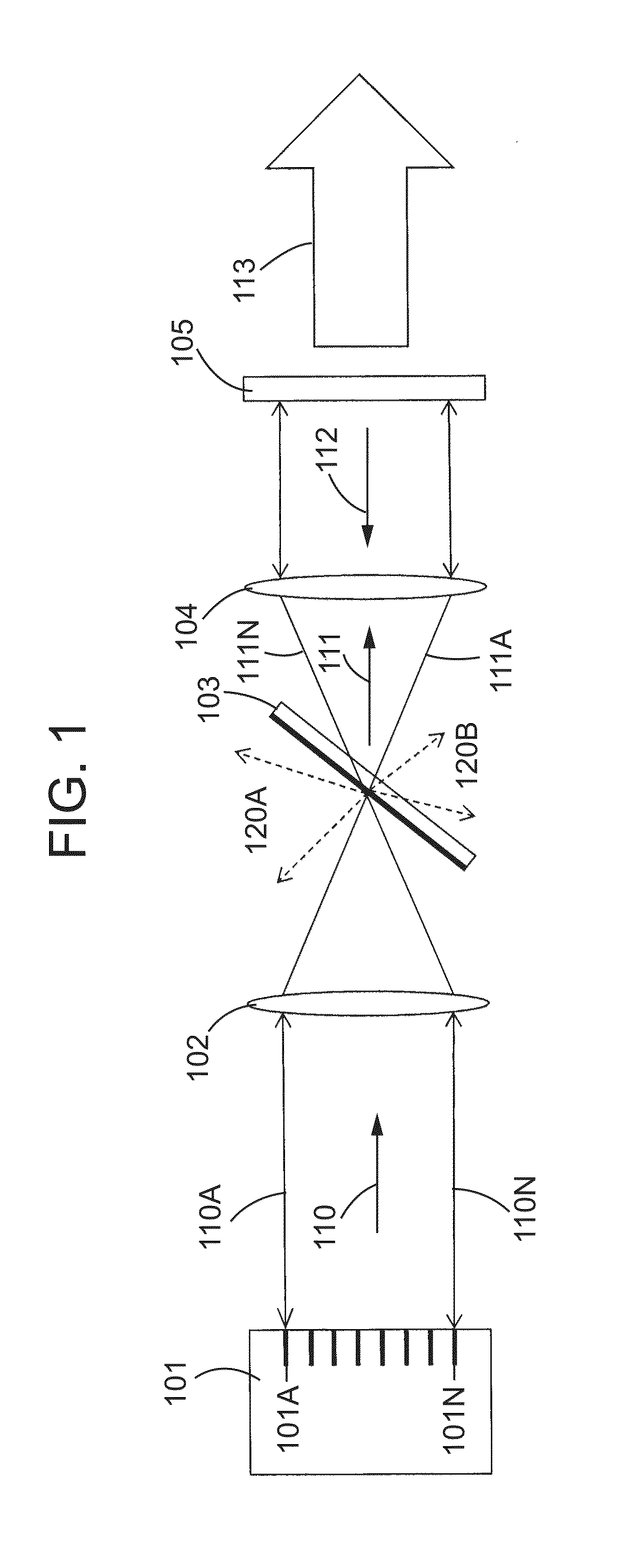
[0053]FIGS. 1-11 illustrate and provide insight into the operation of external resonators that utilize thin-film filters as wavelength selective elements. The embodiments depicted in FIGS. 1 and 10 include laser sources that consist of a plurality of spatially separated individual laser emitters. The individual laser emitters may be diode lasers, fiber lasers, solid-state lasers, or any other type of lasers. The plurality of individual emitters that constitute the laser sources 101 and 1001 may be arranged in a one dimensional array, a two dimensional array, or a variety of other configurations. In some embodiments, the laser sources 101 and 1001 consist of stacks of diode bars, where each bar has a plurality of emitters. Typically, individual diode laser emitters emit beams with an asymmetric beam profile having two perpendicular axes perpendicular to the direction of propagation upon which the beam diverges at disparate rates. The two axes can be identified ...


PUM


Abstract

Wavelength-selective external resonators can be used to greatly increase the output brightness of dense wavelength beam combining (DWBC) system beams by stabilizing the wavelengths of the beams emitted by the individual emitters of the DWBC laser source. The present invention pertains to external resonant cavities that utilize thin-film filtering elements as wavelength-selective elements in external resonators. The present invention further pertains to particular embodiments that utilize thin-film filtering elements in DWBC systems as both output beam coupling elements and wavelength selective elements. The present invention provides advantages over the prior art that include decreased cost, increased fidelity of wavelength selection, and increased wall plug efficiency.

Description

FIELD OF THE INVENTION[0001]The present disclosure relates generally to laser systems and more particularly to systems and methods for narrow-bandwidth laser beam stabilization and multiple laser beam combining.BACKGROUND OF THE INVENTION[0002]Dense wavelength beam combining (DWBC) is a technique for producing a single, high-brightness, multi-spectral output beam from a plurality of narrow spectral bandwidth input beams. DWBC techniques, which have also sometimes been referred to as dense wavelength multiplexing (DWM) techniques in some prior art, enable multiple relatively low-power single wavelength input beams to be superimposed to produce a single, high-power, high-brightness output beam. DWBC techniques enable output beam power to be scaled directly with the sum of the power produced by the plurality of input beams and produce output beams of quality commensurable with the quality of the individual input beams.[0003]In DWBC systems, a plurality of narrow spectral bandwidth, or ...

Claims


Application Information

Patent Timeline
IPC IPC(8): H01S3/13G02B27/10
CPCG02B27/1006H01S3/13H01S5/141H01S5/4012H01S5/4062H01S5/4087
Inventor HUBER, RUDOLFZIMER, HAGENKILLI, ALEXANDERTILLKORN, CHRISTOPHRIED, STEFFEN
Owner TRUMPF LASER GMBH CO KG
Why Eureka
Try Eureka