Fuel storage device

a technology of fuel storage and fuel vapor, which is applied in the direction of internal fittings, transportation and packaging, transportation items, etc., can solve the problems of reducing the amount of evaporated fuel (fuel vapor) generated in the fuel storage chamber of the tank case, ensuring the sealing characteristics by sealing between the wall of the tank case and the bladder film, and reducing the amount of evaporated fuel (fuel vapor)

Inactive Publication Date: 2015-06-04
DENSO CORP
View PDF2 Cites 17 Cited by
  • Summary
  • Abstract
  • Description
  • Claims
  • Application Information

AI Technical Summary

Benefits of technology

[0011]As a result of this fuel storage device, in a state in which the fuel tank is disposed in a vehicle, there is provided the fuel tank that includes the tank case having a projecting shape in section and forming the upper-lower two-tiered fuel storage chamber. The secondary fuel storage chamber (first fuel storage chamber) that is not in contact with the atmosphere at the time of feeding fuel to the fuel tank is provided for this tank case. Accordingly, with joining to component parts attached to the tank case and sealing characteristics with respect to the tank case easily ensured, there can be reduced an area of the fluid level of liquid fuel in direct contact with the fill opening through which liquid fuel is supplied into the fuel storage chamber of the tank case (area of contact with the atmosphere at the time of feeding fuel to the fuel tank). As a consequence, the amount of evaporated fuel (fuel vapor) generated in the fuel storage chamber of the tank case can be decreased.

Problems solved by technology

However, to completely divide the fuel storage chamber in the tank case between the fuel chamber and the air chamber by the bladder film, there raises an issue that a method of joining with component parts such as a pressure control valve, a check valve, a filter element, a fuel pump, a pressure sensor, and a temperature sensor, and ensuring of sealing characteristics by a means for sealing between a wall of the tank case and the bladder film become difficult.
Thus, in the conventional fuel tank system, there has not been achieved a reduction of evaporated fuel (fuel vapor) produced in the fuel storage chamber of the tank case of the fuel tank with the joining to the component parts attached to the tank case of the fuel tank and the sealing characteristics with respect to the tank case easily ensured.

Method used


Image

  • Fuel storage device
  • Fuel storage device
  • Fuel storage device

Examples


Embodiment Construction

[0015]An embodiment will be described in detail below with reference to the accompanying drawings.

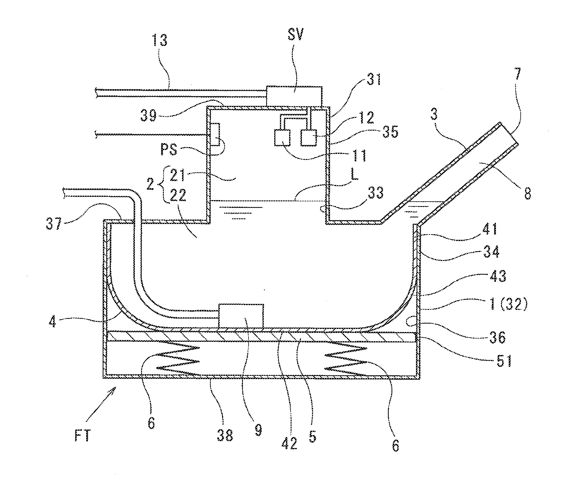
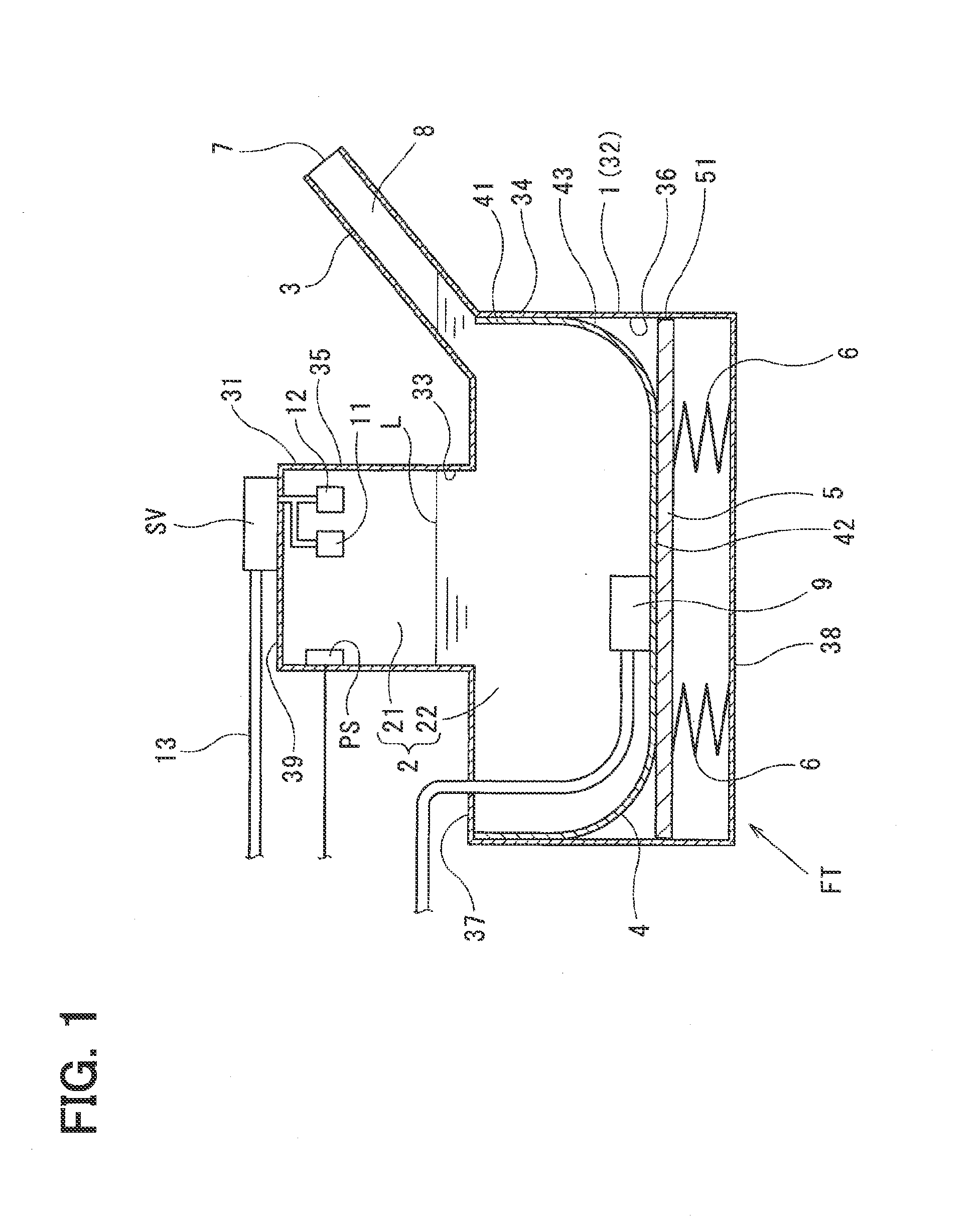
[0016]Configuration of the embodiment will be explained below. FIG. 1 illustrates a fuel tank seal system of the embodiment to which a fuel storage device of the present disclosure is applied.

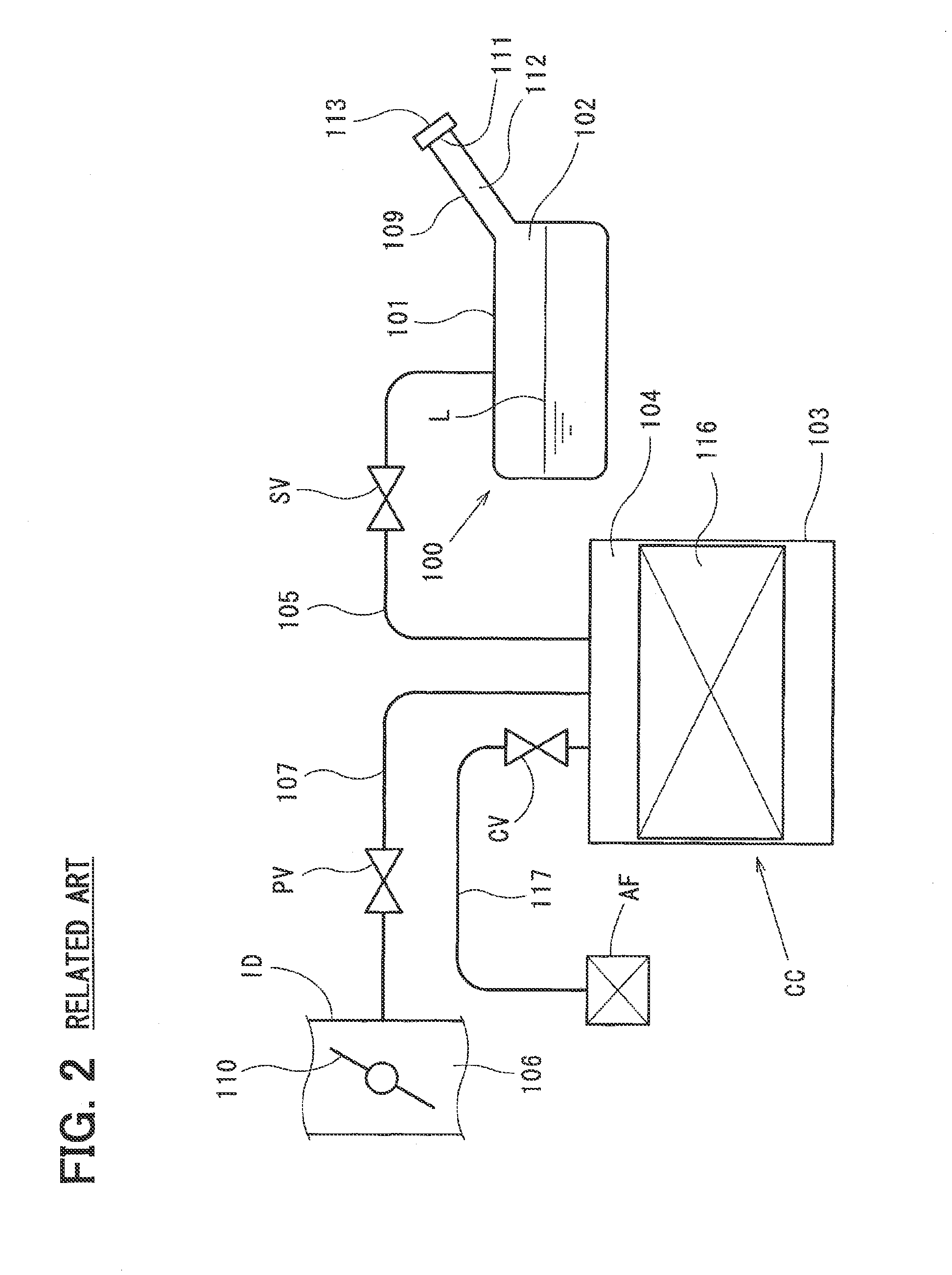
[0017]An evaporated fuel processor of the present embodiment includes the fuel tank seal system that can seal a fuel tank FT by closing a seal valve SV disposed between the fuel tank FT and a canister CC. This fuel tank seal system is disposed in a vehicle such as a hybrid automobile that travels with an internal combustion engine (engine) and an electric motor (motor) as its power source. The fuel tank seal system includes the fuel tank FT, the seal valve SV, the canister CC, and a purge control valve PV, and is connected to an intake pipe ID communicating with a combustion chamber of each cylinder of the engine.

[0018]The engine is an engine for vehicle traveling that is disposed in a vehicle such...


PUM


Abstract

A fuel storage device includes a fuel tank that stores liquid fuel which is fed through a fill opening of a vehicle. The fuel tank includes a tank case and a separating film. The tank case has a projecting shape in section and defines a two-tiered upper-lower fuel storage chamber in a state where the fuel tank is disposed in the vehicle. The separating film is deformable in the tank case and has impermeability against liquid fuel in the fuel storage chamber. The fuel storage chamber includes a primary fuel storage chamber and a secondary fuel storage chamber. The primary chamber is surrounded partly with the separating film and communicates with the fill opening. The secondary chamber projects toward an upper side of the primary chamber in the state where the fuel tank is disposed in the vehicle and communicates with the fill opening only via the primary chamber.

Description

CROSS REFERENCE TO RELATED APPLICATION[0001]This application is based on Japanese Patent Application No. 2013-249954 filed on Dec. 3, 2013, the disclosure of which is incorporated herein by reference.TECHNICAL FIELD[0002]The present disclosure relates to a fuel storage device including a fuel tank that stores liquid fuel (fuel for an internal combustion engine) fed from a fuel fill opening disposed in a vehicle having the internal combustion engine through a fuel feed pipe (filler pipe).BACKGROUND[0003]Conventionally, for a fuel storage device disposed in a vehicle such as an automobile, as illustrated in FIG. 2, to prevent release of evaporated fuel produced in a fuel tank 100 of a vehicle to the atmosphere at the time of feeding fuel to the fuel tank 100, there is proposed an evaporated fuel processor (fuel tank seal system) including a canister CC that can adsorb evaporated fuel generated in a fuel storage chamber 102 in a tank case 101 of the fuel tank 100, a first fuel vapor pa...

Claims


Application Information

Patent Timeline
Patent Type & Authority Applications(United States)
IPC IPC(8): B60K15/03B65D25/02B65D21/08
CPCB60K15/03006B60K2015/0321B65D25/02B65D21/08B60K2015/03072B60K15/03B60K15/03519B60K15/077B60K2015/03171
Inventor OOIWA, HIDETOSHI
Owner DENSO CORP
Why Eureka
Try Eureka