Delayed coking process

a coking process and delay technology, applied in the field of improved delay coking process, can solve the problems of reducing coke yield and enhancing unable to provide information on the reduction of coke yield and increase in gas and liquid yield, and presenting problems in handling of coke, and competing with other low-cost solid fuels

Active Publication Date: 2015-06-04
INDIAN OIL CORPORATION
View PDF3 Cites 7 Cited by
  • Summary
  • Abstract
  • Description
  • Claims
  • Application Information

AI Technical Summary

Benefits of technology

[0038]FIG. 3, illustrate pilot plant data showin

Problems solved by technology

However, this patent does not indicate any reduction of coke yield and enhancement of gas and liquid yields.
However, this patent does not provide any information on

Method used


Image

  • Delayed coking process
  • Delayed coking process
  • Delayed coking process

Examples


example

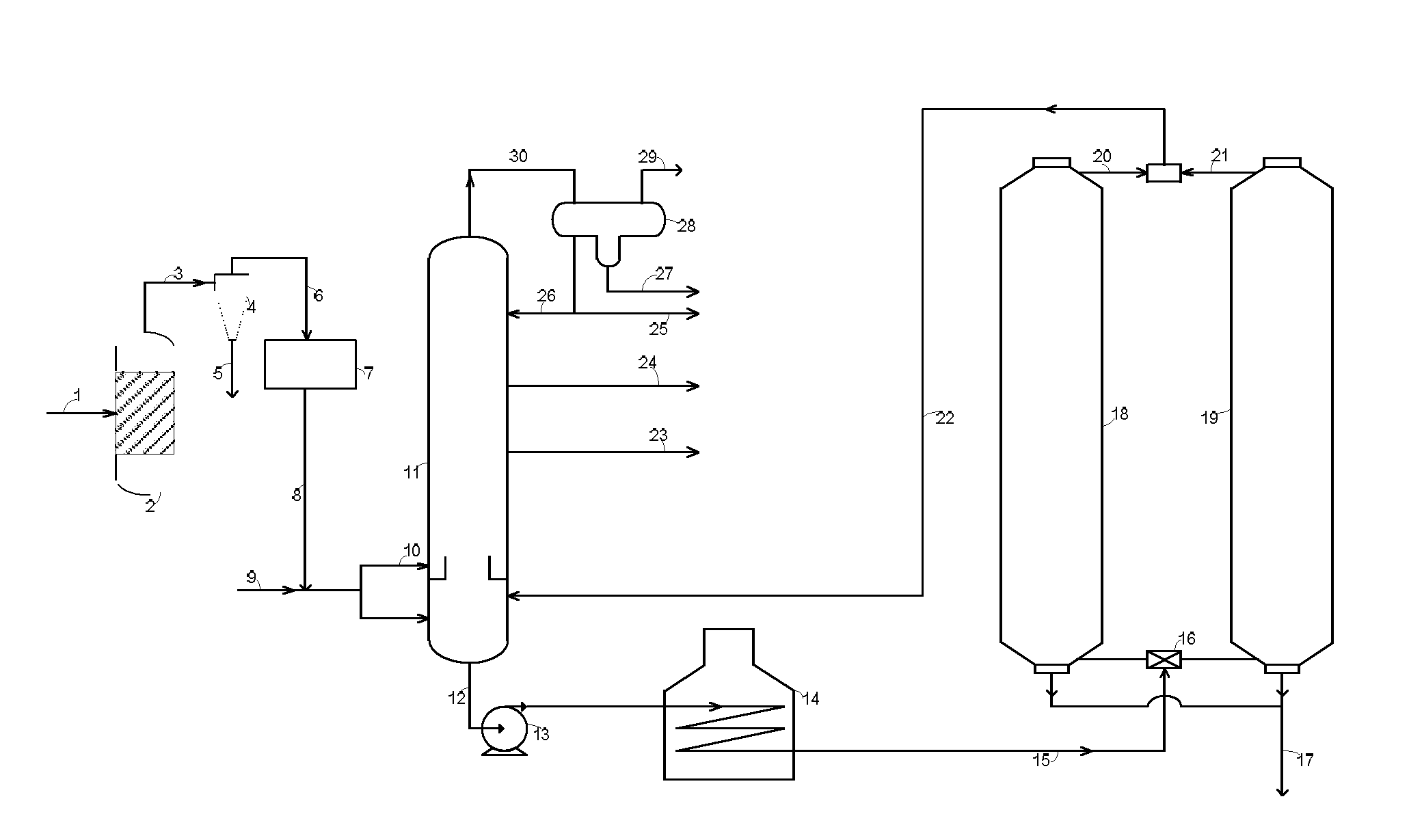
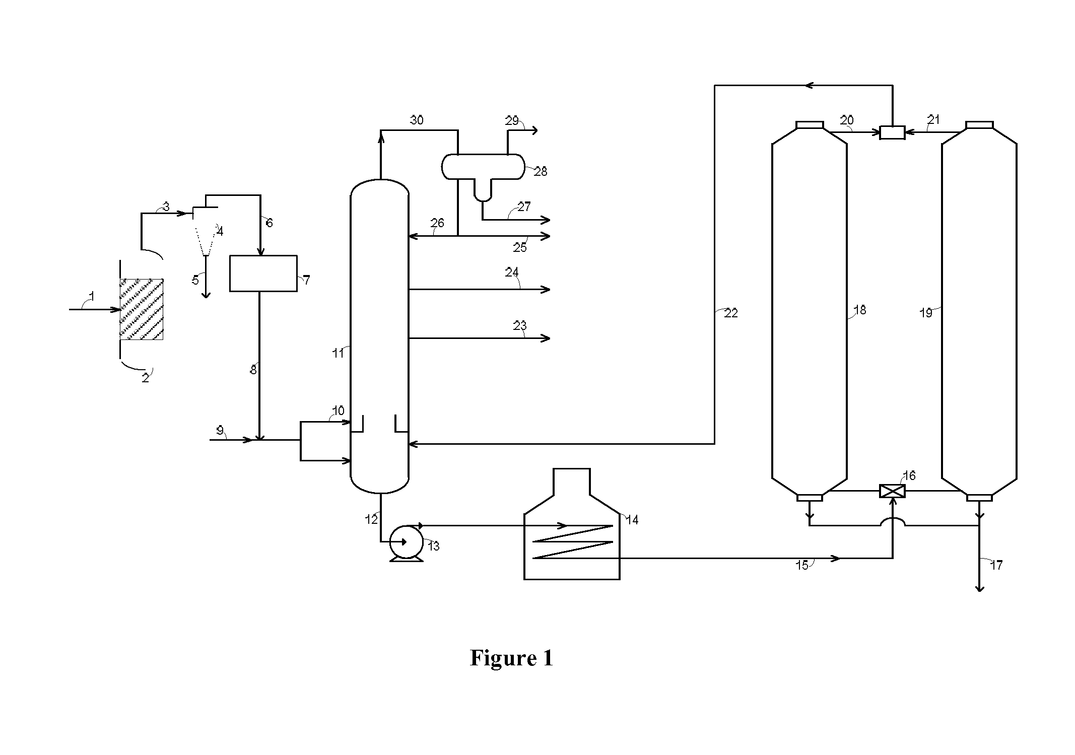
[0081]A Delayed coking pilot plant of 8 Kg / h feed rate was used for carrying out the experiments. Four experiments were conducted using commercially available residual heavy hydrocarbon feedstock (Resid feedstock A) and biooil (containing insoluble pyrolytic lignin, aldehydes, carboxylic acids, carbohydrates, phenols, alcohols and ketones). In one experiment 100 percent Resid feedstock was used and in the other three experiments various mixtures of Resid feedstock and biooil were used.

[0082]The experiments were performed in a Delayed coker pilot plant. The operating conditions for all the experiments were 495° C. feed furnace outlet line temperature, 14.935 psig coke drum pressure, 1 wt % steam addition to the coker feed and a feed rate maintained at about 8 kg / h. The operation was in semi batch mode. The vapors from the coking drums were recovered as liquid and gas products and no coker product was recycled to the coker drum.

[0083]The Delayed coking pilot plant unit was operated on...


PUM


Abstract

The present invention provides a delayed coking process comprising a step of subjecting a mixed feed comprises residual heavy hydrocarbon feedstock and bio oil obtained from fast pyrolysis of lignocellulosic biomass of one or more of Jatropha, Cashew nut, Karanjia and Neem to a delayed coking process and a system for the delayed coking process.

Description

FIELD OF INVENTION[0001]This invention relates to an improved Delayed coking process in which biooil is mixed with a heavy hydrocarbon feedstock passing into a coking zone. In a more specific instance this invention relates to an improved Delayed coking process in which biooil, generated by fast pyrolysis of different sources of biomass, and is added to the heavy hydrocarbon feedstock such as residual oil feed to the Delayed coking process for reduction of coke yield and enhancement of gas and liquid yields.BACKGROUND OF THE INVENTION[0002]Currently, the most common process for heavy oil up-gradation is the Delayed coking process. A Delayed coker operates on the principle of thermal cracking and produces solid coke, gaseous and liquid products from heavy hydrocarbon feedstock. During the coking process, heavy hydrocarbon feedstock are heated in a furnace, passed through a transfer line and discharged into a coking drum. The feedstock is thermally converted to solid coke and vapors. ...

Claims


Application Information

Patent Timeline
IPC IPC(8): C10B57/04C10B27/00C10B53/02C10B31/12C10G9/00C10G55/02
CPCC10B57/045C10G9/005C10B27/00C10B53/02C10B31/12C10G55/02C10B55/00C10G2300/1014C10G2300/107C10G2300/1077Y02E50/10Y02P20/145Y02P30/20
Inventor THAKUR, RAM MOHANARORA, AJAY KUMARDEVI PRASAD, TERAPALLI HARI VENKATARAMACHANDRAN, PRADEEP PONOLYDIXIT, JAGDEV KUMARRAJESH,BHATTACHARYYA, DEBASISPURI, SURESH KUMARKUMAR, BRIJESHRAJAGOPAL, SANTANAMMALHOTRA, RAVINDER KUMAR
Owner INDIAN OIL CORPORATION
Why Eureka
Try Eureka