Piezoelectric motor, robot hand, robot, finger assist apparatus, electronic component conveying apparatus, electronic component inspecting apparatus, liquid feed pump, printing apparatus, electronic timepiece, and projecting apparatus

a technology of electronic components and motors, applied in the direction of generators/motors, mechanical devices, manufacturing tools, etc., can solve the problems of unintentional resonance in the supporting portion, affecting the driving characteristics of piezoelectric motors, etc., and achieve the effect of enhancing the support of the vibrating body and enhancing the accuracy of adjusting the projecting state of light by the optical lens

Inactive Publication Date: 2015-06-11
SEIKO EPSON CORP
View PDF2 Cites 22 Cited by
  • Summary
  • Abstract
  • Description
  • Claims
  • Application Information

AI Technical Summary

Benefits of technology

[0009]The term “rigidity” used in the aspect of the invention means a “nature that resists deformation caused by an external force when the external force is applied”. Examples of the term “the rigidity of the supporting portion is high” include that the amount of deflection when the supporting portion is pressed is small, that the amount of bending when the supporting portion is bent is small, and the amount of twisting when the supporting portion is twisted is small.
[0046]With the projecting apparatus according to the aspect of the invention configured in this manner, since the support of the vibrating body may be enhanced to prevent the vibrating body from being moved by a reaction force that the abutting portion receives from the movable portion without affecting the vibration of the vibrating body, the vibration of the vibrating body is adequately transmitted to the moving portion, and accuracy of adjusting the projecting state of light by the optical lens can be enhanced.

Problems solved by technology

However, with the vibrating body supporting structure as described in JP-A-8-237971, there is a problem that driving characteristics of the piezoelectric motor are affected from the following reasons.
First of all, there is a case where a resonance may occur unintentionally in the supporting portion by the vibration of the vibrating body transmitted to the supporting portion via the coupling portions.

Method used


Image

  • Piezoelectric motor, robot hand, robot, finger assist apparatus, electronic component conveying apparatus, electronic component inspecting apparatus, liquid feed pump, printing apparatus, electronic timepiece, and projecting apparatus
  • Piezoelectric motor, robot hand, robot, finger assist apparatus, electronic component conveying apparatus, electronic component inspecting apparatus, liquid feed pump, printing apparatus, electronic timepiece, and projecting apparatus
  • Piezoelectric motor, robot hand, robot, finger assist apparatus, electronic component conveying apparatus, electronic component inspecting apparatus, liquid feed pump, printing apparatus, electronic timepiece, and projecting apparatus

Examples


Embodiment Construction

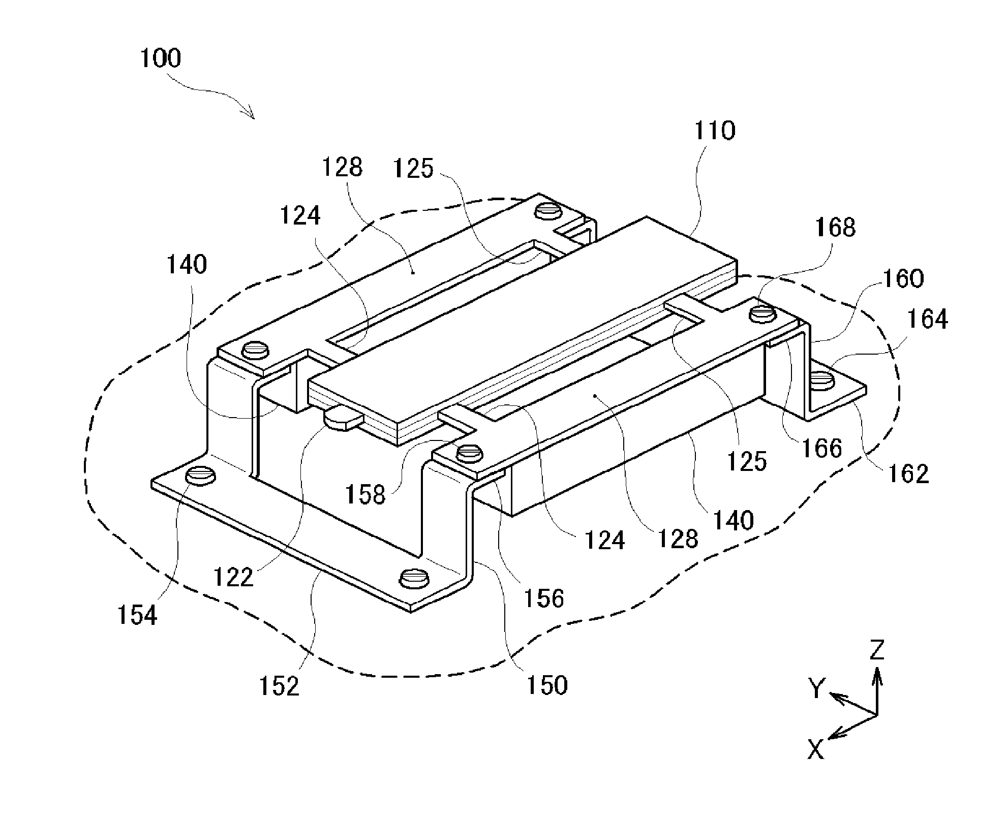
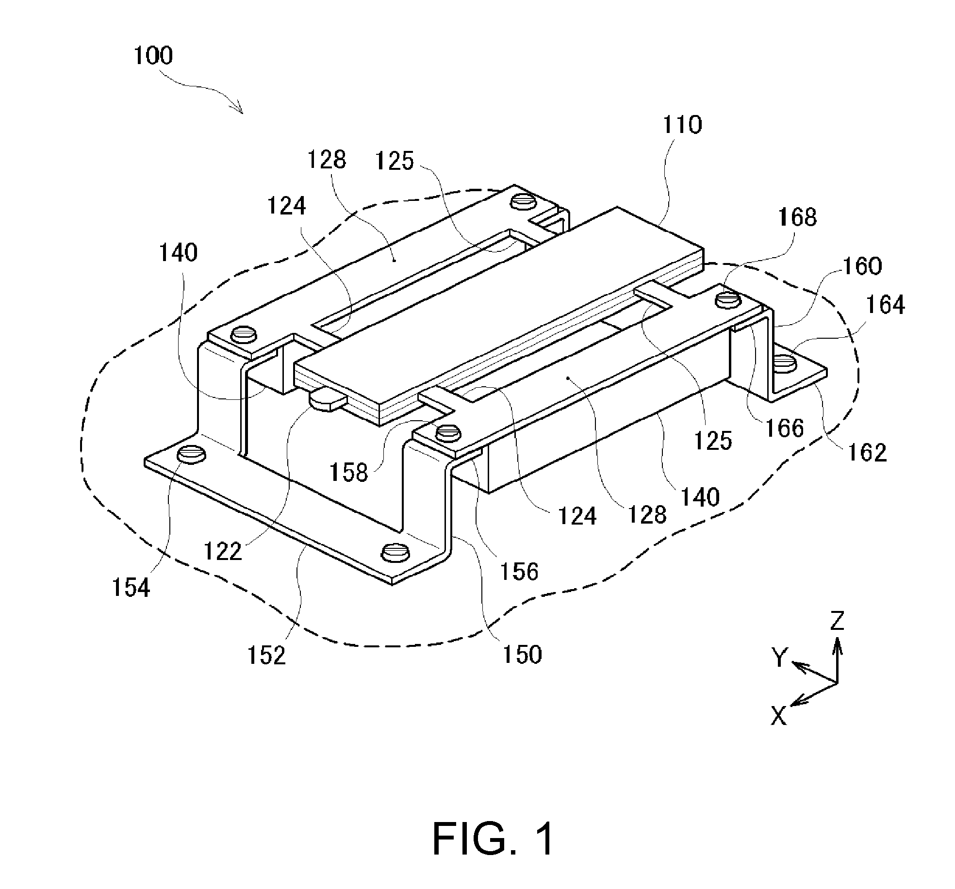
[0070]FIG. 1 is a perspective view illustrating a structure of a piezoelectric motor 100 of an example. As illustrated in the drawing, the piezoelectric motor 100 of the example roughly includes a vibrating body 110 including a piezoelectric material, supporting portions 128 configured to support the vibrating body 110, and two leaf springs (front leaf spring 150 and rear leaf spring 160) configured to bias the vibrating body 110 in a predetermined direction.

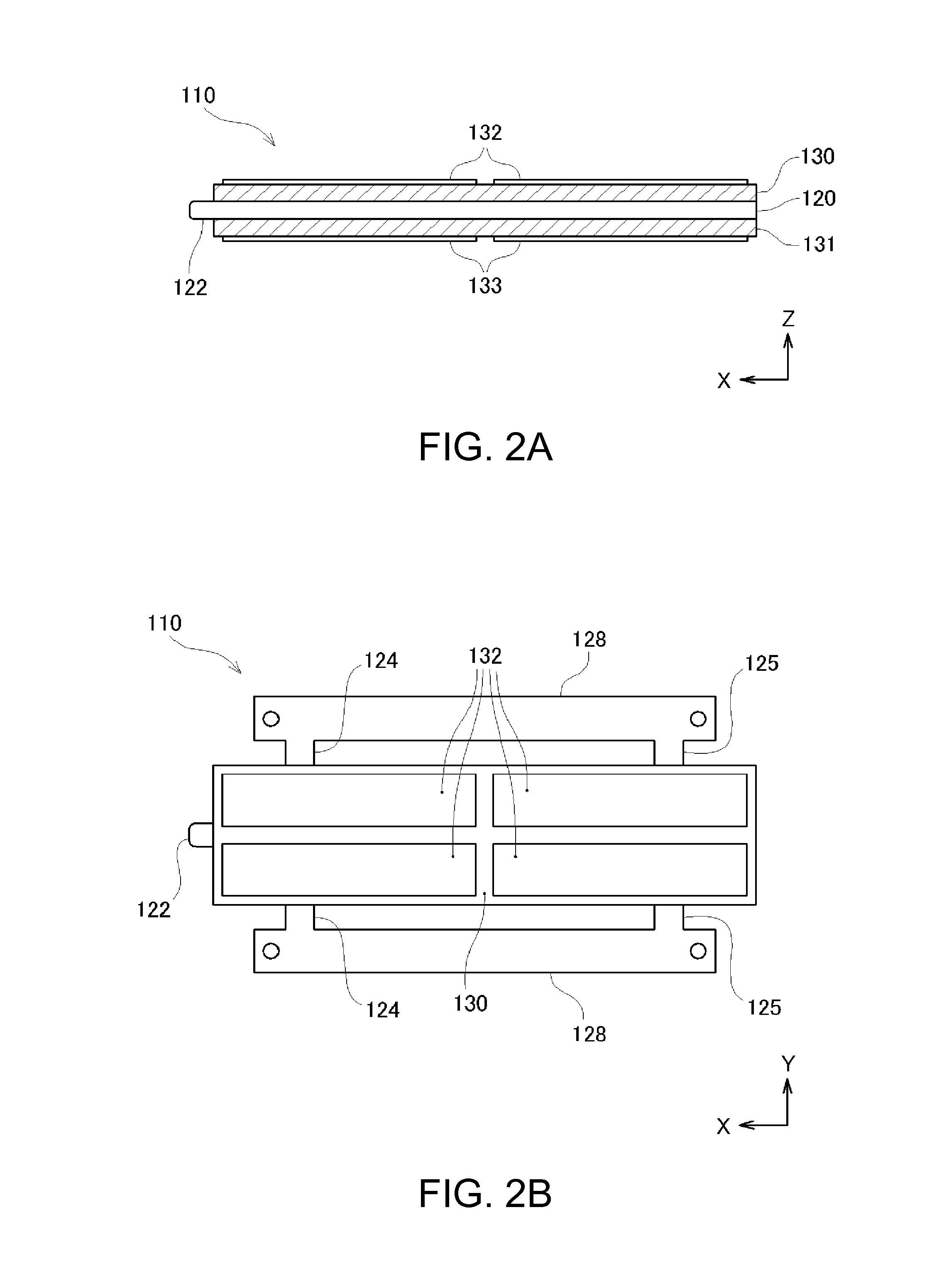
[0071]The vibrating body 110 has a parallelepiped shape, and is provided with a projecting portion 122 configured to abut against an object to be driven by the piezoelectric motor 100 on an end surface in the longitudinal direction. A detailed structure of the vibrating body 110 will be described with reference to other drawings. The longitudinal direction of the vibrating body 110 is referred below to as an X-direction. In the drawing, the short direction of the vibrating body 110 orthogonal to the X-direction is referred to as...


PUM


Abstract

A supporting portion disposed in parallel to a joint portion to which a vibrating body capable of generating a bending vibration is jointed and configured to support the vibrating body and the joint portion is provided, and the joint portion and the supporting portion are coupled with a plurality of coupling portions. The supporting portion has rigidity higher than that of the joint portion.

Description

BACKGROUND[0001]1. Technical Field[0002]The present invention relates to a piezoelectric motor, a robot hand, a robot, a finger assist apparatus, an electronic component conveying apparatus, an electronic component inspecting apparatus, a liquid feed pump, a printing apparatus, an electronic timepiece, and a projecting apparatus.[0003]2. Related Art[0004]A piezoelectric motor configured to drive an object by vibrating a vibrating body including a piezoelectric material is known. The piezoelectric motor is characterized by being capable of obtaining a large drive force although being smaller than an electromagnetic motor using an electromagnetic force, and being capable of positioning the object at a high resolution capability.[0005]The piezoelectric motor is operated in the following principle. First of all, a voltage is applied to a vibrating body to cause the vibrating body to generate a predetermined vibration. Then, an end portion of the vibrating body moves along a specific tra...

Claims


Application Information

Patent Timeline
Patent Type & Authority Applications(United States)
IPC IPC(8): B25J15/02B25J17/00H02N2/04H01L41/09H01L41/053
CPCB25J15/0253H01L41/0933H01L41/053H02N2/04B25J17/00H02N2/004H02N2/0055H02N2/006H02N2/103Y10T74/20329H10N30/88
Inventor KAMIJO, KOICHIMIYAZAWA, OSAMU
Owner SEIKO EPSON CORP
Why Eureka
Try Eureka