Dielectric-free metal-only dipole-coupled broadband radiating array aperture with wide field of view

Inactive Publication Date: 2015-06-11
CUBIC CORPORATION
View PDF8 Cites 39 Cited by
  • Summary
  • Abstract
  • Description
  • Claims
  • Application Information

AI Technical Summary

Benefits of technology

[0004]In one of its aspects, the invention relates to the design and implementation of ultra-broadband (i.e., up to several octaves or up to and/or surpassing decade bandwidth), dielectric-free, metal-only, very-low-profile array of radiating apertures capable of supporting transmit and receive operation with arbitrary polarization states. The array of radiating apertures may be structurally-simple and suitable for additive manufacturing. The array of radiating apertures in accordance with the present invention may provide an antenna that is capable of scanning to angles approachi

Problems solved by technology

Dielectrics may introduce additional losses especially at higher frequencies, and can contribute to additional weight, size and cost.
In addition, a top thic

Method used


Image

  • Dielectric-free metal-only dipole-coupled broadband radiating array aperture with wide field of view
  • Dielectric-free metal-only dipole-coupled broadband radiating array aperture with wide field of view
  • Dielectric-free metal-only dipole-coupled broadband radiating array aperture with wide field of view

Examples


Embodiment Construction

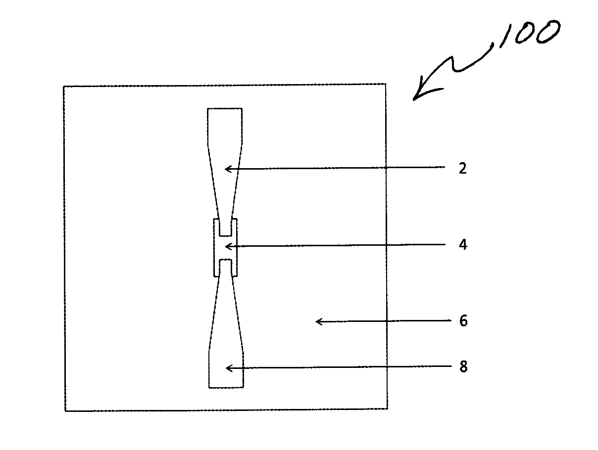
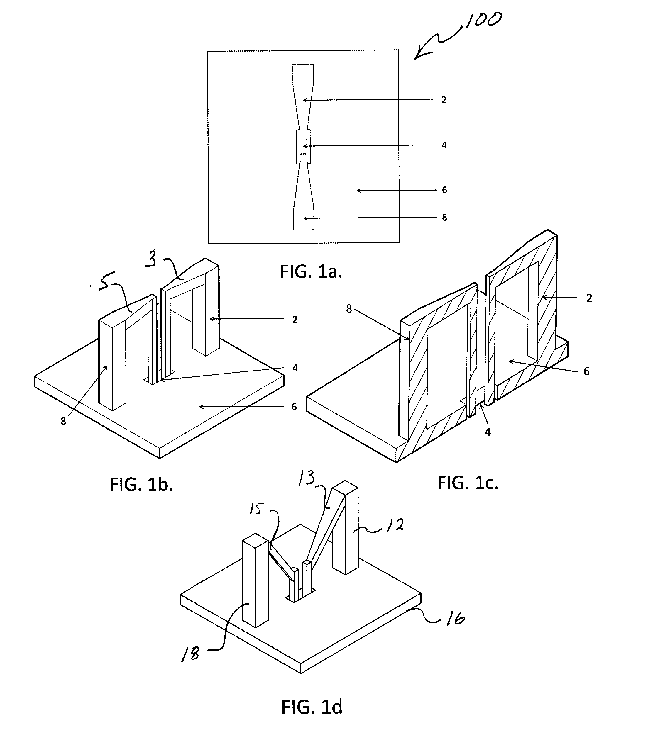
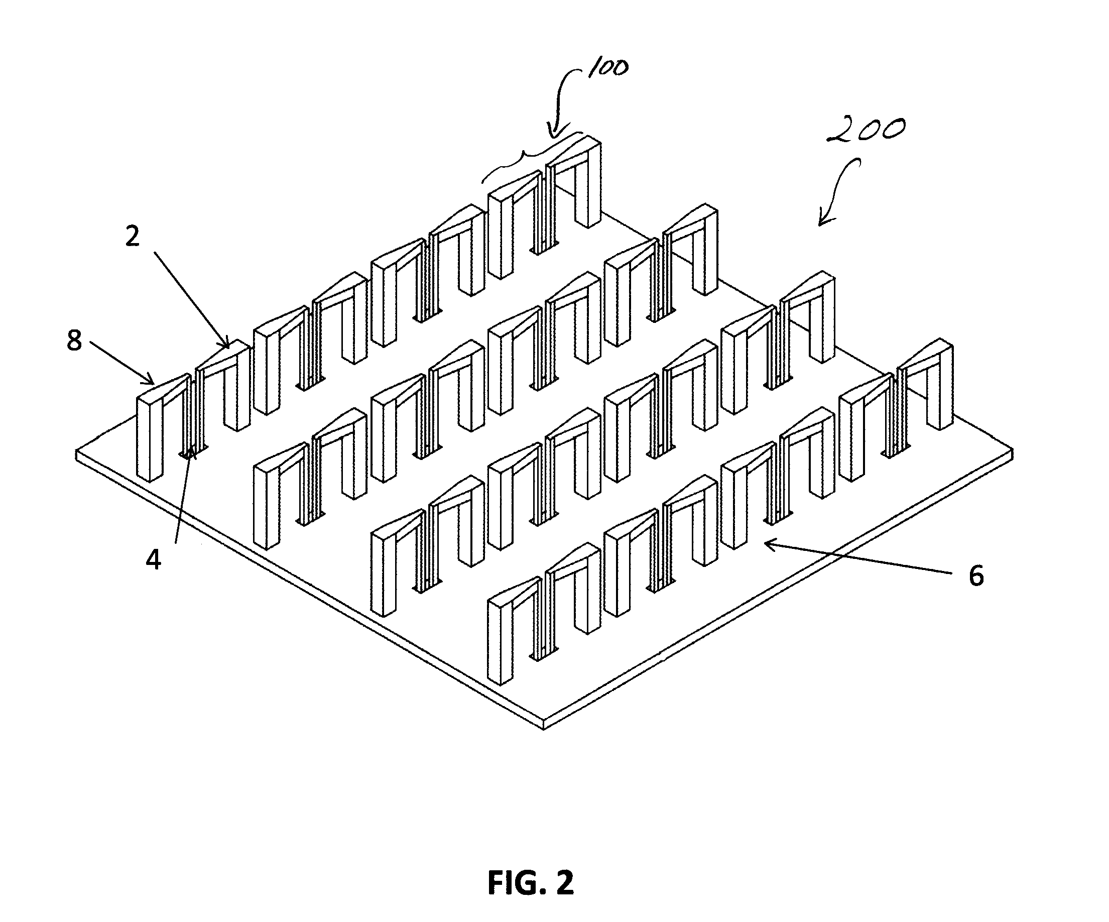
[0017]Referring now to the figures, wherein like elements are numbered alike throughout, FIGS. 1a-1c schematically illustrate an exemplary configuration of a unit cell 100 of a single-polarized antenna in accordance with the present invention. The antenna may include a differentially fed shorted arms 2, 8 of the antenna positioned above a ground surface (such as ground plane 6 or other surface shape, e.g., a conformal surface) and fed via a feed region 4, which may include one or more openings. (Though exemplary configurations of present invention may be illustrated as having a ground “plane”, other surface shapes, such as conformal surfaces, may be provided for grounding.) The arms 2, 8 may cooperate to provide a dipole. The feed region 4 may be provided with no wall separating the feed points for the two differentially-fed shorted arms 2, 8. Alternatively, a wall 30 may be provided as illustrated in FIGS. 3a-3b. The arms 2, 8 may have a cross-sectional dimension that varies along ...


PUM


Abstract

Dielectric-free, metal-only, dipole-coupled broadband radiating array aperture with wide field of view.

Description

RELATED APPLICATIONS[0001]This is application claims the benefit of priority of U.S. Provisional Application No. 61 / 914,693, filed on Dec. 11, 2013, the entire contents of which application are incorporated herein by reference.FIELD OF THE INVENTION[0002]The present invention relates generally to radiating array apertures, and more particularly, but not exclusively, to coupled-dipole broadband arrays which may be metal-only and dielectric-free.BACKGROUND OF THE INVENTION[0003]There are still unmet demands from defense and commercial markets for very low profile array antennas capable of supporting transmit and receive operations with arbitrary polarization states and the ability to scan down to angles approaching the grazing regime with acceptable active reflection coefficients. Besides just the aforementioned major electrical requirements, such prospective arrays have to be of high radiation efficiency and low insertion loss along with their advanced structural properties. Such str...

Claims


Application Information

Patent Timeline
IPC IPC(8): H01Q9/28H01Q21/26
CPCH01Q21/26H01Q9/28
Inventor BORYSSENKO, ANATOLIY O.VANHILLE, KENNETHCANNON, BENJAMIN L.
Owner CUBIC CORPORATION
Why Eureka
Try Eureka