Flyback quick start driving circuit and driving method

a fast-starting, driving circuit technology, applied in the direction of electric variable regulation, process and machine control, instruments, etc., can solve the problems of high standby power consumption of the circuit, time-consuming circuit start, and difficulty in balancing the effects of starting time and stopping time, so as to achieve low power consumption

Active Publication Date: 2015-06-11
TCL CHINA STAR OPTOELECTRONICS TECH CO LTD
View PDF2 Cites 12 Cited by
  • Summary
  • Abstract
  • Description
  • Claims
  • Application Information

AI Technical Summary

Benefits of technology

[0003]Aiming at the above-mentioned problems, the present disclosure provides a flyback quick start driving circuit and a driving method. Starting of the driving circuit operating in the driving method can be speeded up, and in the meantime, its power loss is reduced.
[0023]Compared with the prior art, the flyback quick start driving circuit provided in the present disclosure has the advantages of quick start and low power consumption. At the starting stage of the circuit, the voltage required during starting is quickly pulled up to the starting voltage by charging. At the stabilizing stage of the circuit, the voltage of the auxiliary winding of the transformer is monitored. The driving unit keeps working even if the charging process is stopped, so that the circuit enters a standby state with low power consumption. The present disclosure is particularly suitable for driving a high-power load which needs quickly start, such as backlights of a liquid crystal display (LCD) panel.

Problems solved by technology

On the condition that the two pull-up resistors R12 and R13 have high values of resistance, such as a megohm-level value, the charging of the capacitor C11 is relatively slow, which results in that the starting of the circuit is time consuming.
On the condition that the two pull-up resistors R12 and R13 have low-values of resistance, such as a kiloohm-level value, the starting of the circuit can be speeded up, but the costs it brings is high standby power consumption of the circuit.
Accordingly, it is difficult to balance the effects between the starting time and the standby power consumption of the flyback quick start driving circuit in the prior art.

Method used


Image

  • Flyback quick start driving circuit and driving method
  • Flyback quick start driving circuit and driving method
  • Flyback quick start driving circuit and driving method

Examples


Embodiment Construction

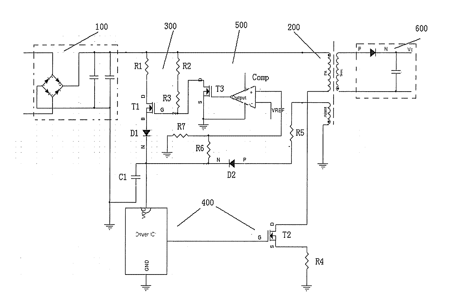
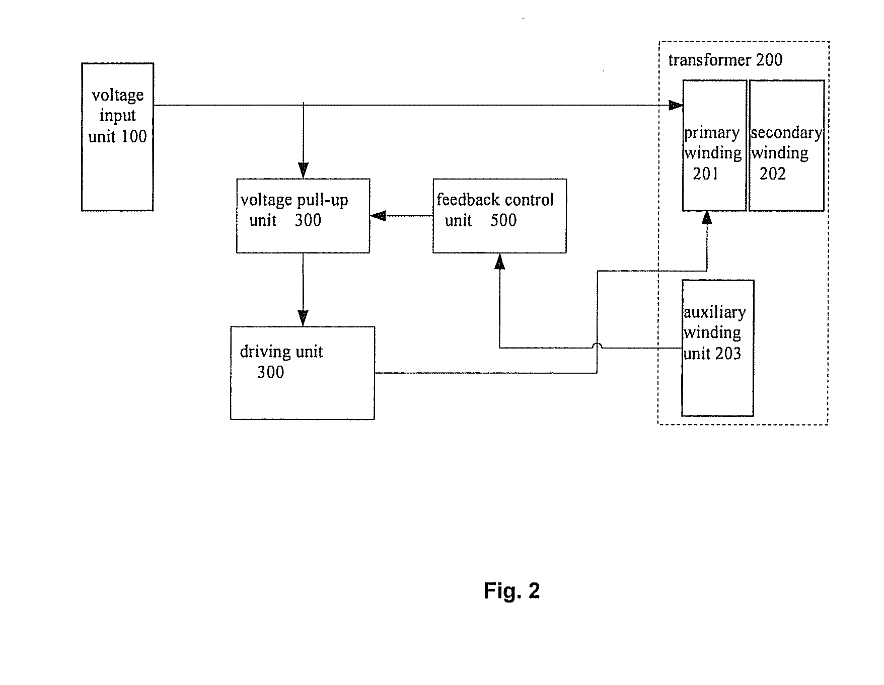
[0028]FIG. 2 shows a block diagram of a flyback quick start driving circuit according to the present disclosure. The circuit includes a voltage input unit 100, a transformer 200, a voltage pull-up unit 300, a driving unit 400, and a feedback control unit 500, wherein, the voltage input unit 100 provides a direct-current voltage.

[0029]The transformer 200 includes a primary winding 201 and a secondary winding 202 coupled on the different sides of the transformer, and an auxiliary winding 203 coupled with the primary winding 201 on the same side of the transformer, wherein the first end of the primary winding 201 is electrically connected with the voltage input unit 100 to receive the direct-current voltage.

[0030]The input of the voltage pull-up unit 300 is electrically connected with the voltage input unit 100 to receive the direct-current voltage, and the output is electrically connected with the power port of the driving unit 400 to perform a charging process based on the direct-cur...


PUM

PropertyMeasurementUnit
voltageaaaaaaaaaa
direct-current voltageaaaaaaaaaa
power factoraaaaaaaaaa

Abstract

The present disclosure discloses a flyback quick start driving circuit, comprising: a voltage input unit, a transformer including a primary winding, a secondary winding, and an auxiliary winding, a driving unit for controlling the primary winding of the transformer, a voltage pull-up unit, and a feedback control unit. The voltage pull-up unit performs a charging process according to the direct-current from the voltage input unit, so as to enable the output voltage rise up to a starting voltage which is input the driving unit. The driving unit output a control signal to drive the primary winding. Thus, a voltage is created across the auxiliary winding. The feedback control unit gets the voltage of the auxiliary winding, and determines whether to stop the charging of the voltage pull-up unit or not according to the voltage of the auxiliary winding. The circuit can be started quickly and have lower loss of the power.

Description

FIELD OF THE INVENTION[0001]The present disclosure relates to a load start driving technology, and particularly, relates to a flyback quick start driving circuit and a driving method.BACKGROUND OF THE INVENTION[0002]A driving circuit for driving a high-power load (such as an LED tube serving as back lights of a liquid crystal display device) needs to meet the requirements of high power factor, constant output current, electric isolation, quick start, low power consumption and the like. At present, a flyback quick start driving circuit is widely used for the driving operation of the above-mentioned high-power load due to the advantages of its simplicity, good voltage regulation performance, stronger load capacity, and more resistant to interference. FIG. 1 shows a structural schematic diagram of a flyback quick start driving circuit in the prior art, wherein the input of the driving circuit is input of a full-bridge rectifier filter circuit 10, the output of the full-bridge rectified...

Claims


Application Information

Patent Timeline
Patent Type & Authority Applications(United States)
IPC IPC(8): H02J7/00G02F1/1335H01L25/00H02M7/06H02M3/335H01C1/16H02M1/00H02M1/36
CPCH02J7/0063H02M3/33569H02J7/0052G02F1/1336H01L25/00H02M7/06H01C1/16H02M1/36H02M3/335H01L2924/0002G09G3/3406G09G2330/02G09G2330/022H02M1/0006H01L2924/00H02J7/00
Inventor WANG, ZHAOCAO, DAN
Owner TCL CHINA STAR OPTOELECTRONICS TECH CO LTD
Why Eureka
Try Eureka