Heating device

Active Publication Date: 2015-06-11
NICHIAS CORP
View PDF6 Cites 8 Cited by
  • Summary
  • Abstract
  • Description
  • Claims
  • Application Information

AI Technical Summary

Benefits of technology

[0078]The support member may contain, in addition to the above-mentioned bio-soluble inorganic fibers, reinforcing fibers such as silica-alumina fibers, silica fibers, alumina fibers, zirconia fibers, glass fibers, rock wool or the like.
[0079]Further, the support member may contain, in addition to inorganic fibers, an organic binder, an inorganic binder or the like. For these, it is possible to use a normal binder as long as it does not inhibit the advantageous effects of the invention. As the organic binder, starch, an acrylic resin, polyacrylamide, pulp, acrylic emulsion or the like can be exemplified. As the inorganic binder, colloidal silica such as anionic colloidal silica and cationic colloidal silica, fumed silica, zirconia sol, titania sol, alumina sol, bentonite, kaolin or the like can be exemplified. The amount of these binders is 1 to 50 wt %, more preferably 3 to 30 wt % and further preferably 5 to 20 wt % relative to the support member.
[0080]The support member may further contain inorganic powder. The inorganic powder is ceramic powder such as zircon, calcium carbonate, cordierite, wollastonite, silica, alumina, titania, zirconia, silicon nitride and silicon carbonate and carbon powder such as carbon black, for example. The amount of the inorganic powder is normally 0 wt % to 80 wt %, more preferably 0 wt % to 50 wt %, and further preferably 0 wt % to 30 wt % relative to the support member.
[0081]The heat-generating member used in the heating device is not particularly restricted. For example, an iron-chromium-aluminum-based metal heat-generating member or a nickel-chromium-based metal heat-generating member can be given. As such a metal heat-generating member, a coil-like or wavy metal heat-generating member can be mentioned.
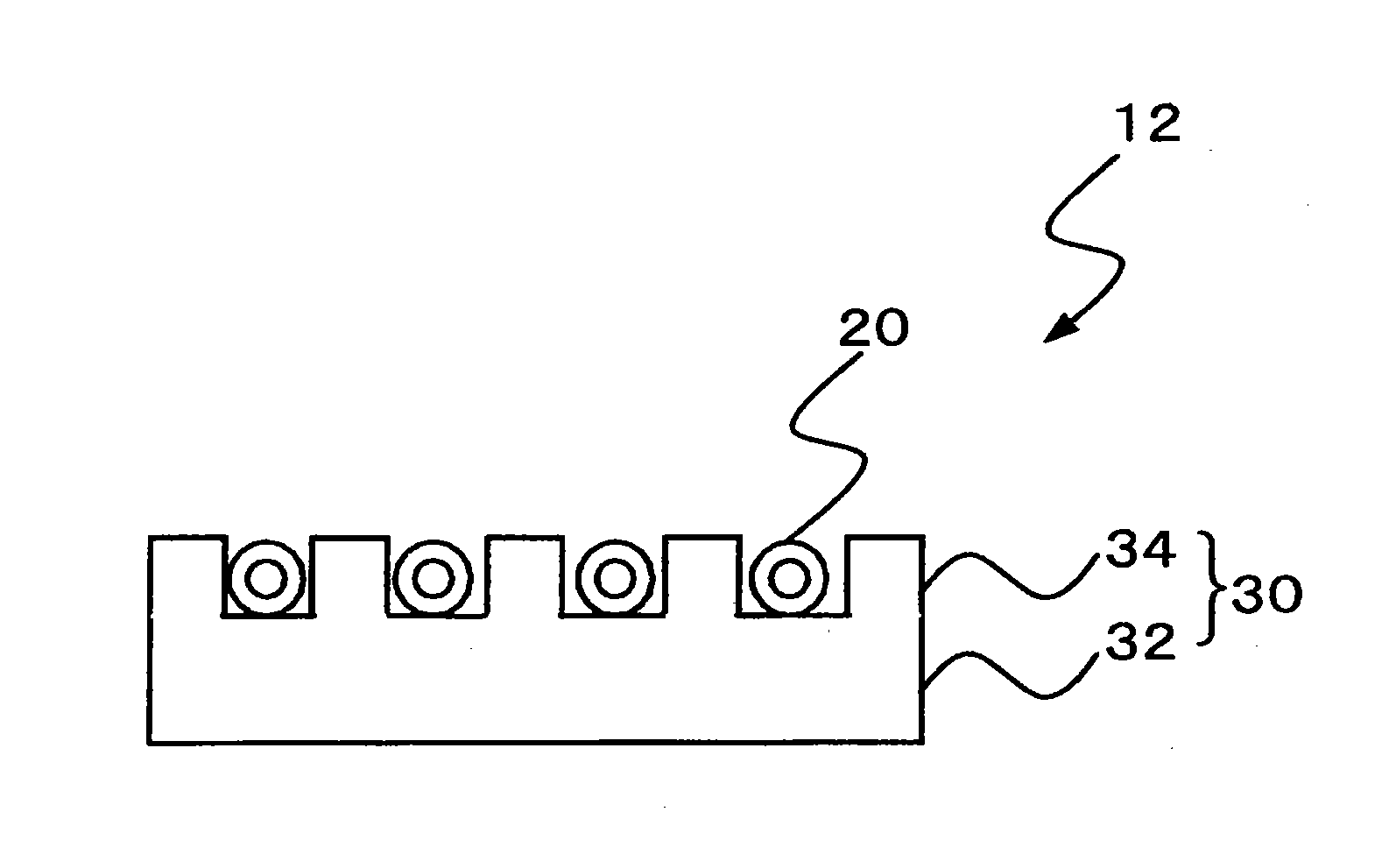
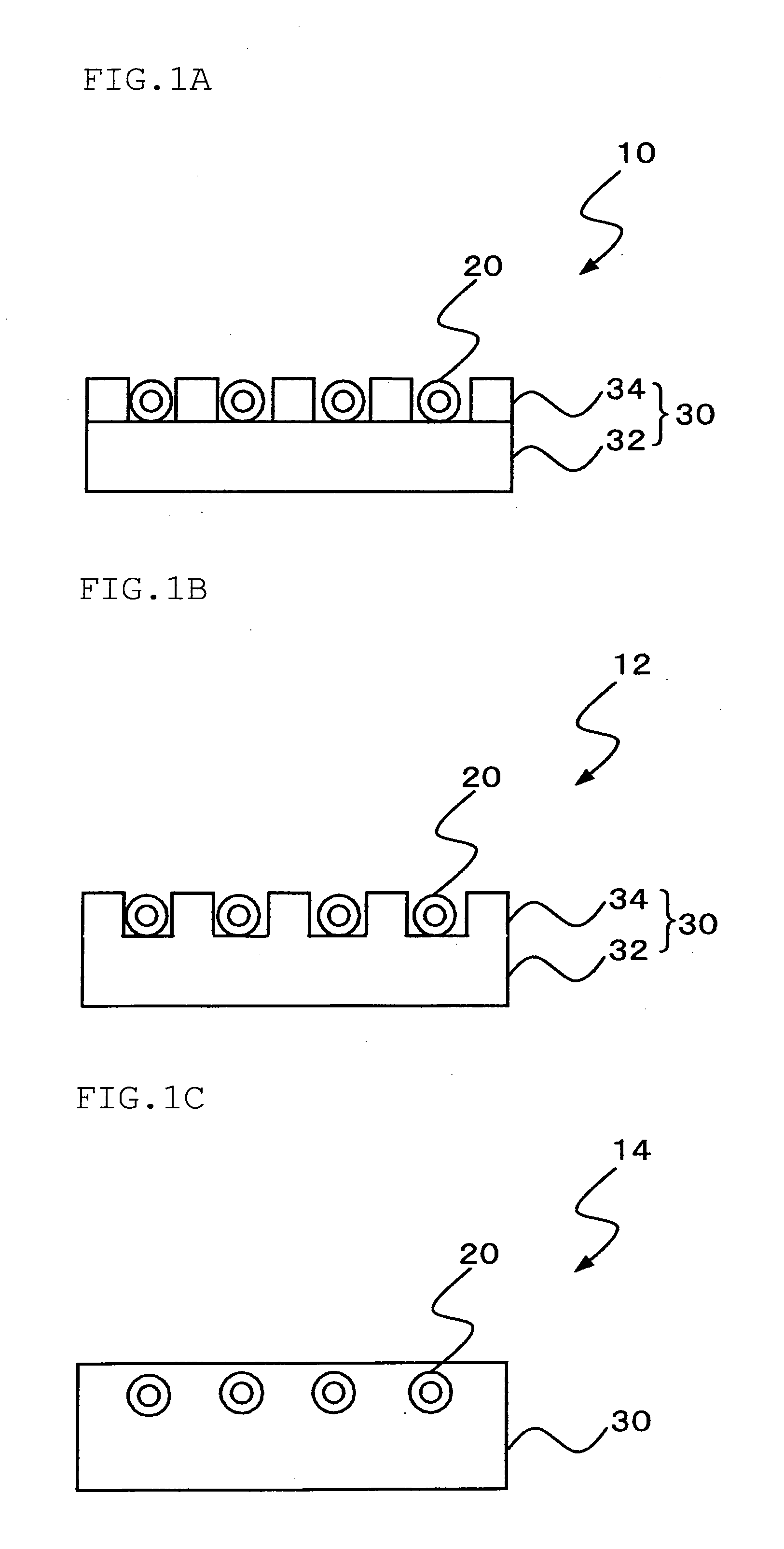
[0082]As an example of the method for coating the support member (bio-soluble inorganic fibers) with a silica-containing treatment agent, a hardening treatment using silica will be explained. A heat-insulating member (shaped product, board) is produced from bio-soluble inorganic fibers. Normally, a heat-insulating member is produced by subjecting a slurry that contains a raw material such as inorganic fibers and a binder to dehydration forming. The support member may be formed (for example, in the example shown in FIG. 1A, a based part and a side wall are laminated. In the example shown in FIG. 1B, processing (cutting) is conducted to obtain a desired shape, or the like) before the heat-insulating member is subjected to a hardening treatment, or a hardening treatment may be conducted after the support member is formed.
[0083]The heating device shown in FIG. 1C can be produced by setting the heat-generating member in a predetermined mold at the time of dehydration forming, followed by a hardening treatment after the forming. In order to adjust the position where a heat-generating member is embedded, dehydration shaping may be conducted plural times. If coating of fibers with silica may become insufficient when a hardening treatment is conducted after the embedding of a heat-generating member, a hardening treatment may be conducted during a dehydration shaping process.

Problems solved by technology

On the other hand, recently, a problem caused by inhalation of inorganic fibers by a human body and invasion of the inhaled fibers to the lung has been pointed out.

Method used


Image

  • Heating device
  • Heating device
  • Heating device

Examples


production example 2

Production of a Board (Heat-Insulating Member)

[0101]An organic board and an inorganic board were produced in the same manner as in Production Example 1, except that bio-soluble fibers B (SiO2 content: 76 mass %, CaO content: 4 mass %, MgO content: 18 mass % and Al2O3 content: 2 mass %) (dissolution ratio in physiological saline: 23.1%) were used instead of bio-soluble fibers A.

production example 3

Production of a Board (Heat-Insulating Member)

[0102]An organic board and an inorganic board were produced in the same manner as in Production Example 1, except that inorganic fibers C (SiO2 content: 47 mass %, and Al2O3 content: 52 mass %) (dissolution ratio in physiological saline: 0.1%) were used instead of bio-soluble fibers A.

treatment example 1

Hardening Treatment with Silica

[0103]The organic boards and the inorganic boards obtained in Production Examples 1 to 3 (density: 250 kg / m3) were treated (immersed for 1 to 10 seconds) with a hardening liquid formed of an alkaline colloidal silica (pH about 9, solvent: water), and the surfaces thereof were hardened and dried. The density was 300 kg / m3. After the hardening, the strength was increased. The hardness of the hardened organic and inorganic boards was measured by means of a durometer (Durometer Type C, manufactured by Kobunshi Keiki Co., Ltd.). The results are shown in Table 1.

[0104]The organic board and the inorganic board obtained in Production Example 1 were evaluated without conducting a hardening treatment. The hardness was measured by the same method as mentioned above. The results are shown in Table 1.

TABLE 1Fibers (A)Organic boardInorganic boardBeforeBeforehardeningAfter hardeninghardeningAfter hardeningHardness (°)50854075


PUM

PropertyMeasurementUnit
wt %aaaaaaaaaa
temperatureaaaaaaaaaa

Abstract

A heating device 10 including a heat-generating member 20 and a support member 30 that supports the heat-generating member 20 and comprises bio-soluble inorganic fibers, wherein the bio-soluble inorganic fibers do not contact directly the heat-generating member 20 or contact of the bio-soluble inorganic fibers with the heat-generating member 20 is reduced.

Description

TECHNICAL FIELD[0001]The invention relates to a heating device that has a heat-generating member such as an electric heater, and a heat-insulating support member.BACKGROUND ART[0002]Conventionally, as an electric heater structure (heating device) having a configuration in which a helically-wound, coiled electric wire (heating coil) is supported by an insulating material, one in which a kneaded product prepared by adding an inorganic binder to ceramic fibers or the like and by adjusting them is formed in a plate-like shape to allow it to serve as a support member and a heating coil is attached thereto is known, for example (Patent Document 1, for example).[0003]On the other hand, recently, a problem caused by inhalation of inorganic fibers by a human body and invasion of the inhaled fibers to the lung has been pointed out. Under such circumstances, bio-soluble inorganic fibers that do not or hardly cause problems even when inhaled by a human body have been developed (Patent Document ...

Claims


Application Information

Patent Timeline
Patent Type & Authority Applications(United States)
IPC IPC(8): H05B3/06
CPCH05B3/06H05B3/265H05B2203/012C04B35/6224C04B2235/3206C04B2235/3208C04B2235/72C03C13/00C03C25/002C03C25/42C04B35/62849C03C2213/02C04B2235/77C04B2235/96C04B2235/9669C04B35/632
Inventor MIHARA, TETSUYAYONAIYAMA, KENKISHIKI, TOMOHIKOISAKA, YUTA
Owner NICHIAS CORP
Why Eureka
Try Eureka