
Liquid supplying apparatus

a technology of liquid supply apparatus and liquid supply pipe, which is applied in the direction of liquid surface applicators, electrical devices, coatings, etc., can solve the problems of increasing the cost of processing apparatus including such pumps, difficult pipe routing, and difficulty in ejecting processing liquid, so as to reduce the length of processing liquid flow and reduce pressure loss

Inactive Publication Date: 2015-06-18
TOKYO ELECTRON LTD
View PDF4 Cites 7 Cited by
  • Summary
  • Abstract
  • Description
  • Claims
  • Application Information

AI Technical Summary

Benefits of technology

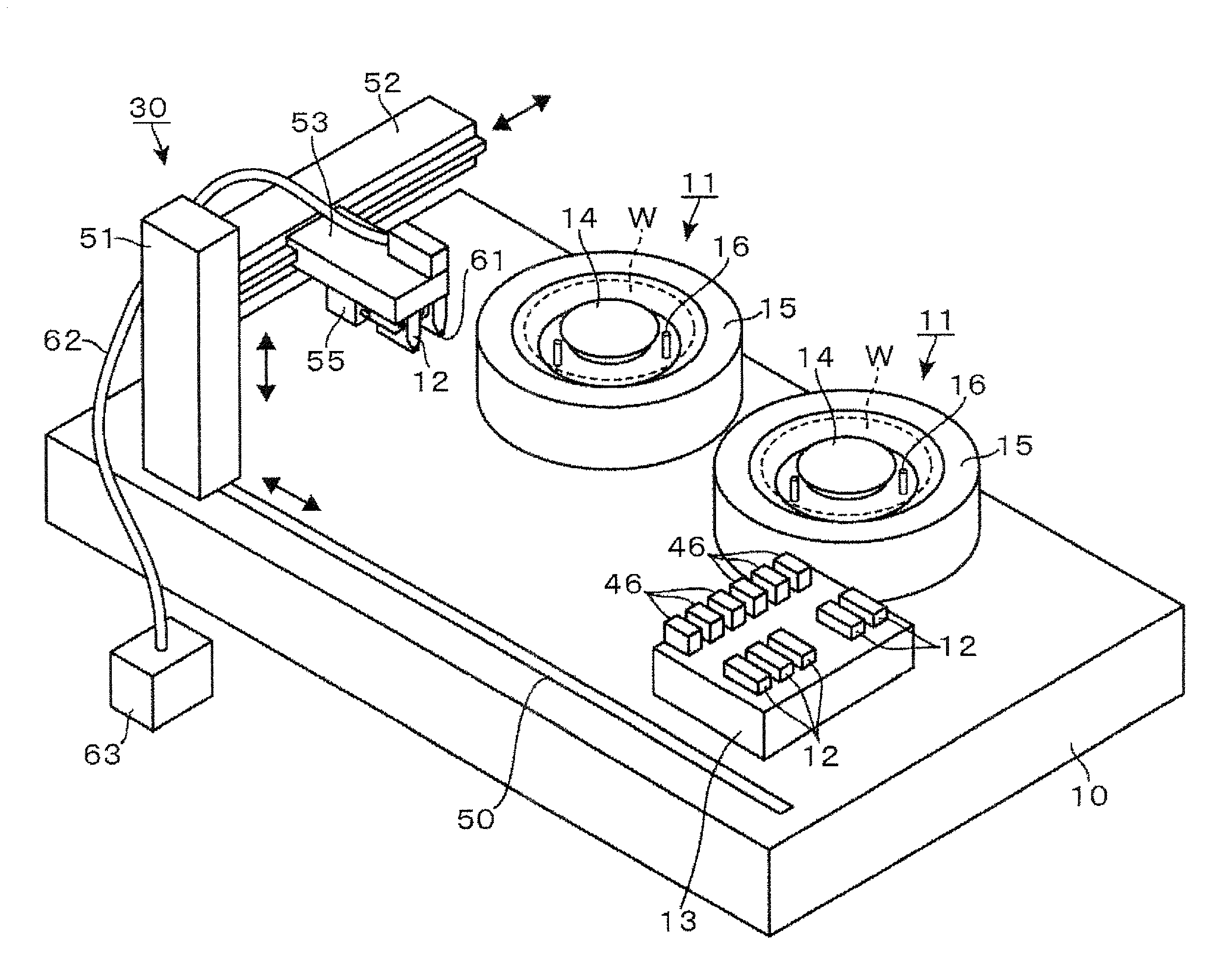
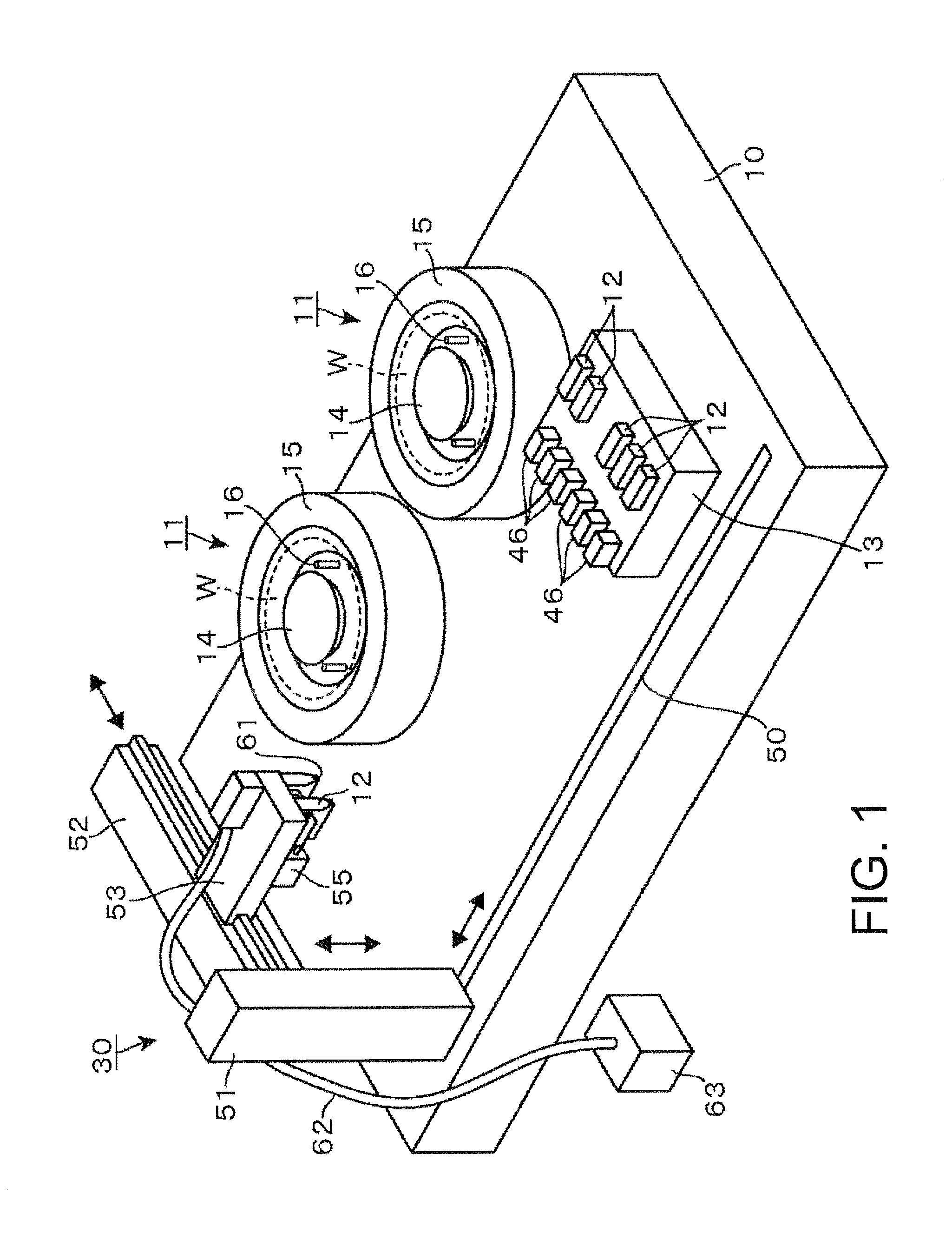
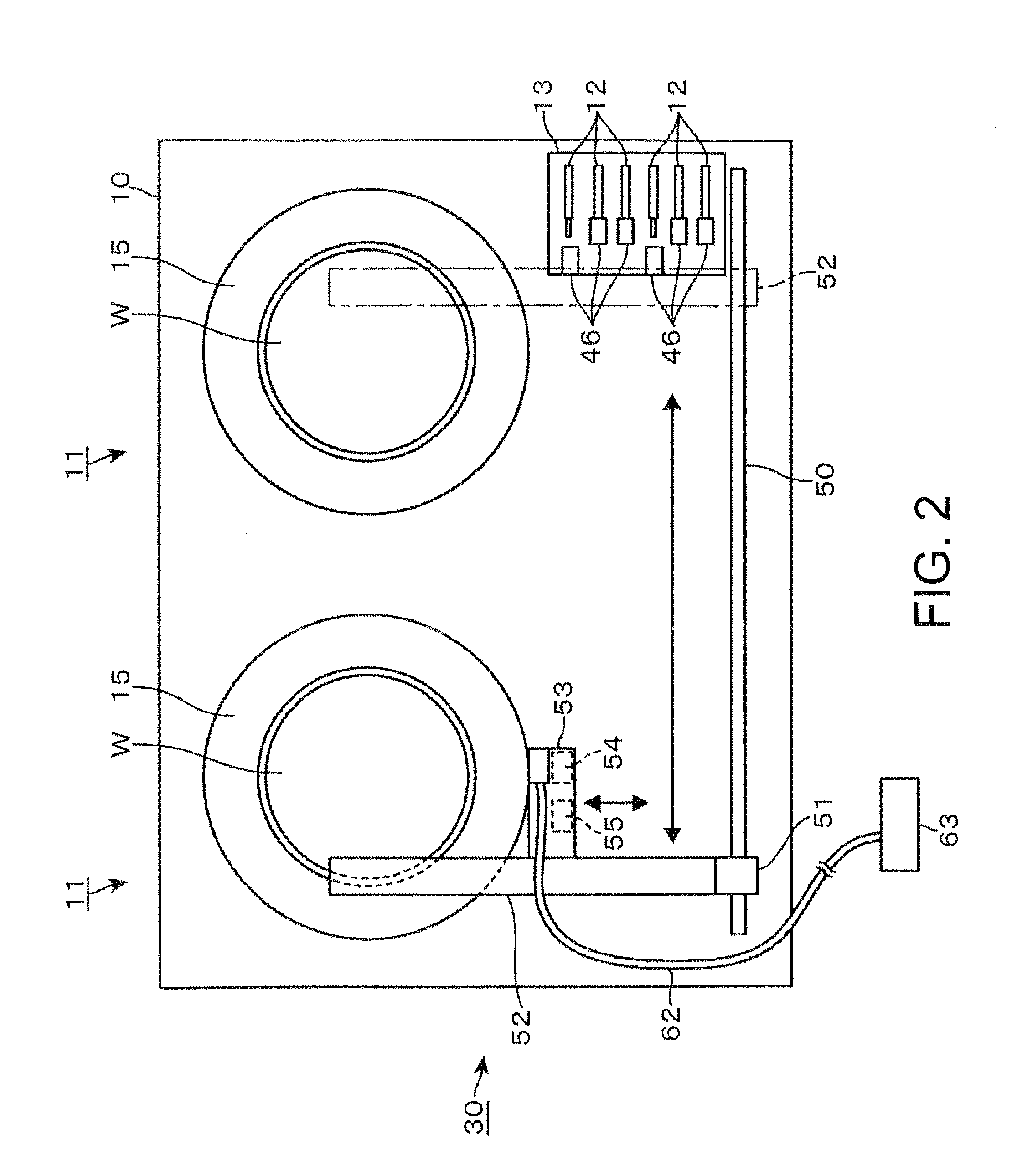
This invention provides a liquid supplying apparatus that can quickly and efficiently eject processing liquid onto a process object without complicating the apparatus. The apparatus is designed with a reservoir chamber and an ejecting port integrated, reducing the length of the processing liquid flow and minimizing pressure loss. Additionally, a separate replenishing port prevents contamination of the ejecting port during processing liquid replenishment.

Problems solved by technology

Higher viscosity of the processing liquid makes it more difficult to eject the processing liquid.
However, if a pump having a larger capacity is employed to increase the processing liquid-ejecting rate, the processing apparatus including such a pump becomes more expensive.
If processing liquid-feeding pipes having a larger internal diameter are employed to increase the processing liquid-ejecting rate, routing of the pipe becomes difficult and the layout of the apparatus and the workability of the operators are restricted.
It is impossible to set the charging rate, at which the processing liquid is drawn into the pump, to be so high, because a high charging rate results in generation of bubbles in the processing liquid.

Method used


Image

  • Liquid supplying apparatus
  • Liquid supplying apparatus
  • Liquid supplying apparatus

Examples


experiment 1

[0124]Resist liquid was ejected onto wafers W having a diameter of 450 mm, while changing the ejection amount of the resist liquid. The spread area in which the resist liquid spreads (expands) on the surface of each wafer W was observed. In detail, after an amount of the resist liquid had been ejected to a central portion of the wafer W while the wafer W was rotated about the vertical axis at a rotating speed, the radius of the resist liquid (resist film) spreading in a circle on the surface of each wafer W was measured.

[0125]The result is described below. As shown in FIG. 25, when 15 grams of the resist liquid was ejected to the wafer W rotating at 600 rpm, the resist liquid spread in a circle having a radius of 150 mm. Thus, it can be understood that 15 grams of resist liquid was sufficient to coat the whole surface of a wafer W having a diameter of 300 mm with the resist liquid. It can be also understood that 30 grams of the resist liquid was required to coat the whole surface of...

experiment 2

[0126]The next experiment was conducted to examine the relationship between the resist liquid discharging pressure (i.e., the pressure applied to the space 25a to eject the resist liquid from the nozzle 21) and the amount of the resist liquid ejected from the nozzle 21, in a case where the resist liquid stored in the cartridge 12 is ejected by pressurizing the cartridge 12. The result is described below. As shown in FIG. 26, it can be understood that the pressure and the ejection amount of the resist liquid were closely correlated with each other. In addition, in a case where the pressure applied to the cartridge 12 was fixed at a given value, the correlation between the ejection time during which the resist liquid was being ejected, and the ejection amount of the resist liquid was examined. FIG. 27 shows the result. It can be understood that the ejection time of the resist liquid and the ejection amount of the resist liquid were closely related to each other.

experiment 3

[0127]An experiment was conducted to examine how the ejection time of the resist liquid gave an impact on the quality of a resist film. When the resist liquid was ejected at a very slow ejection rate of 0.08 ml / second (the ejection time was about 400 seconds), the film thickness was non-uniform in a plane of the wafer W, as indicated by white squares (Experiment 3-1) in the graph of FIG. 28. On the other hand, when the ejection time was 20 seconds, a uniform film thickness profile was obtained, as indicated by white circles (Experiment 3-2) in the graph of FIG. 28. It can be said that if the resist liquid ejection rate is low, in other words, if the time period from the starting of the resist liquid ejection to the completion of the resist liquid ejection is long, the resist liquid ejected earlier may become dried and solidified. It can be also said that, when the resist liquid is supplied to a wafer W having a diameter of 450 mm at the same ejection speed for a wafer W having a dia...


PUM


Abstract

An embodiment of a liquid supplying apparatus for supplying a processing liquid to a process object includes: a processing liquid cartridge including: a reservoir chamber for storing the processing liquid; an ejecting port for ejecting the processing liquid stored in the reservoir chamber; a pusher unit for pushing the processing liquid stored in the reservoir chamber outward through the ejecting port; and a replenishing port for replenishing the processing liquid into the reservoir chamber; a standby unit having a standby area where the processing liquid cartridge is standing-by; a transport mechanism that transports the processing liquid cartridge between the standby unit and a location where the processing liquid cartridge supplies the processing liquid to the process object; and an actuating mechanism provided in the transport mechanism that drives the pusher unit to push the processing liquid stored in the reservoir chamber.

Description

CROSS-REFERENCE TO RELATED APPLICATIONS[0001]This application is based upon and claims the benefit of priority from Japanese patent application No. 2013-257033 filed on Dec. 12, 2013, the entire contents of which are incorporated herein by reference.FIELD OF THE INVENTION[0002]The present invention relates to a liquid supplying apparatus for supplying a processing liquid to a process object.BACKGROUND ART[0003]A series of steps for manufacturing semiconductor devices include a step of supplying a processing liquid, such as a thinner, a resist liquid, a polyimide or an adhesive, to a semiconductor wafer (hereinafter simply referred to as “wafer”) as a substrate (process object). Higher viscosity of the processing liquid makes it more difficult to eject the processing liquid. As the wafer diameter increases, the amount of the processing liquid required for coating the whole surface of the wafer increases. In order to suppress the throughput reduction, the processing liquid is required...

Claims


Application Information

Patent Timeline
Patent Type & Authority Applications(United States)
IPC IPC(8): B05B9/03B05B12/08B05B15/02
CPCB05B9/03B05B12/081B05B15/025H01L21/6715B05B15/55
Inventor FUNAKOSHI, HIDEOKUBOTA, MINORU
Owner TOKYO ELECTRON LTD
Learn More