Planetary gear device

a technology of gear device and planetary gear, which is applied in the direction of gearing details, gearing, transportation and packaging, etc., can solve the problems of degrading processability and increasing production cost, and achieve the effect of reducing production cost and reducing stirring resistance of lubricant oil

Active Publication Date: 2015-06-18
KAWASAKI HEAVY IND LTD
View PDF6 Cites 6 Cited by
  • Summary
  • Abstract
  • Description
  • Claims
  • Application Information

AI Technical Summary

Benefits of technology

[0013]In this structure, the ring gear oil supply hole and a weir are formed in the baffle unit disposed between the planet gears adjacent to each other, to achieve reduction in stirring resistance of the lubricant oil and lubricating of the ring gear, while change of a design of the weir according to, for example, specifications of a device to which the gear device is applied, is facilitated since the weir member in which the weir is formed, is provided separately from the baffle unit.
[0014]In a planetary gear device according to one embodiment of the present invention, a front plate that supports one end portion of a planet shaft serving as a rotary shaft of each of the plurality of planet gears is connected by using a connecting member which is fastened in an axial direction, to a bottom wall located at an axial end portion, of the collection chamber of the baffle unit, on a side opposite to the discharge outlet side. More specifically, for example, the connecting member may include a bolt and a nut that is screwed on the bolt, and the bolt may be inserted into the front plate and the baffle unit from the front plate side, and the nut may be screwed on an end of the bolt on the collection chamber side of the baffle unit. In this structure, when the front plate is to be mounted to the bottom wall of the collection chamber, the connecting member can be fastened in the axial direction in a state where the weir member that is separately formed is not mounted. Therefore, assembling of the planetary gear device having the baffle unit that includes the weir to assuredly supply lubricant oil to the ring gear, is facilitated, thereby reducing production cost.
[0015]In a planetary gear device according to one embodiment of the present invention, the weir member may be fitted into the discharge outlet, and may be axially retained by a diameter-reducible ring-shaped member. In this structure, in assembling of the planetary gear device, for example, fastening of the connecting member in the axial direction in a state where the weir member that is separately formed is not mounted, is facilitated.

Problems solved by technology

Therefore, in a case where the weir is integrated with the baffle, the design of the entirety of the baffle needs to be changed according to change of the design of the weir, which is one of causes of increase in production cost.
Moreover, when a portion of the outlet of the baffle is covered with the weir, it may be difficult to perform an operation of attaching a front plate to the gear device, resulting in processability being degraded in some cases.

Method used


Image

  • Planetary gear device
  • Planetary gear device
  • Planetary gear device

Examples


Embodiment Construction

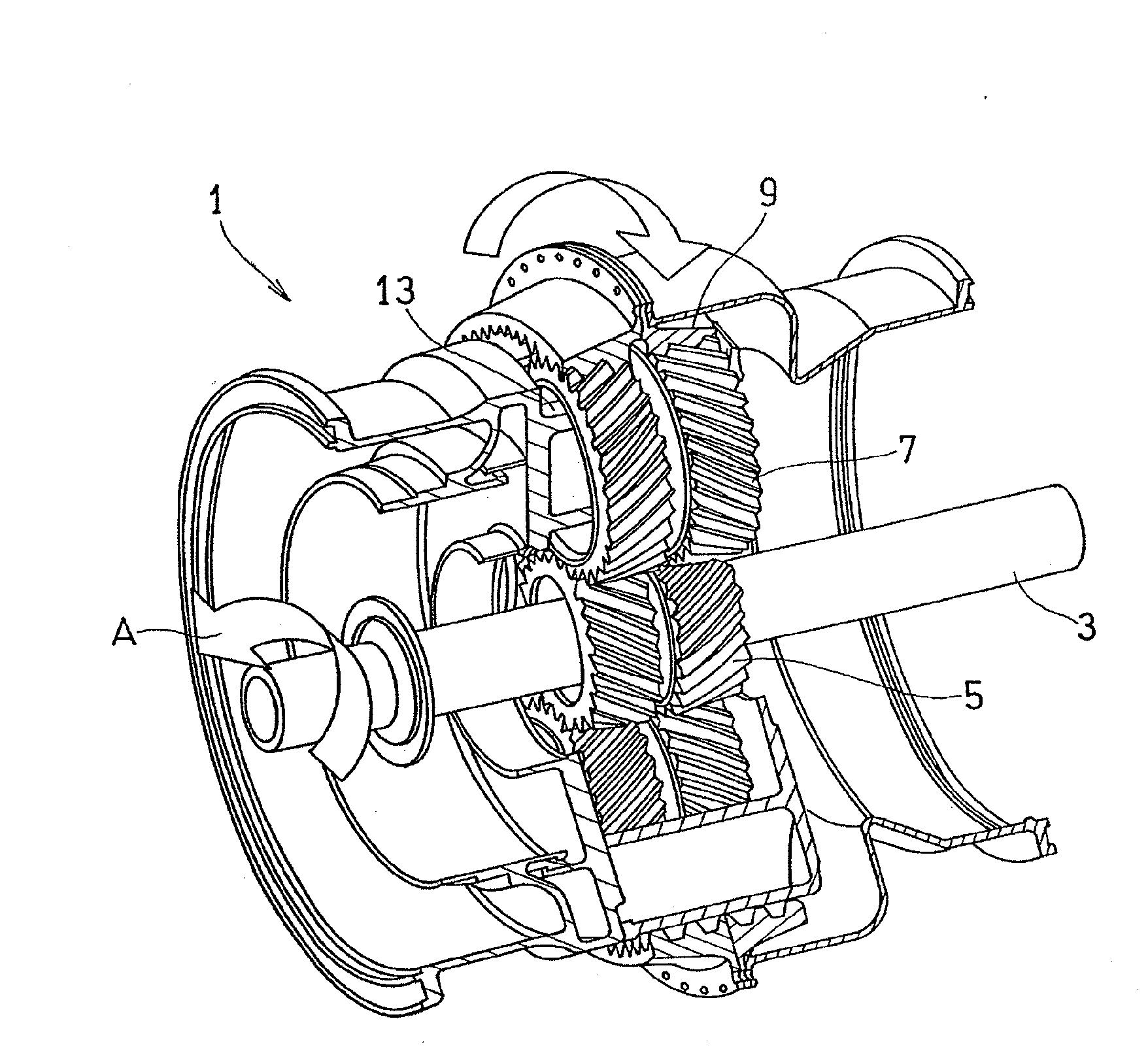
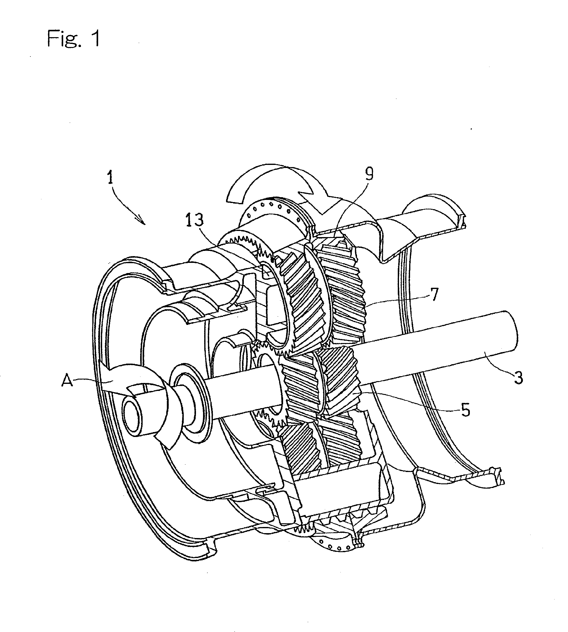
[0028]Hereinafter, embodiments of the present invention will be described with reference to the drawings. FIG. 1 is a perspective view showing a planetary gear device 1 according to one embodiment of the present invention. The planetary gear device 1, which may be mounted to an engine of a helicopter or an aircraft, is connected to a gas turbine engine (not shown) via an input shaft 3, to transmit power of the gas turbine engine to two rotors (not shown), as independent outputs, respectively. In the following description, a side (the lower left side in FIG. 1), in the axial direction, on which the gas turbine engine is disposed is referred to as a front side, and the opposite side is referred to as a rear side.

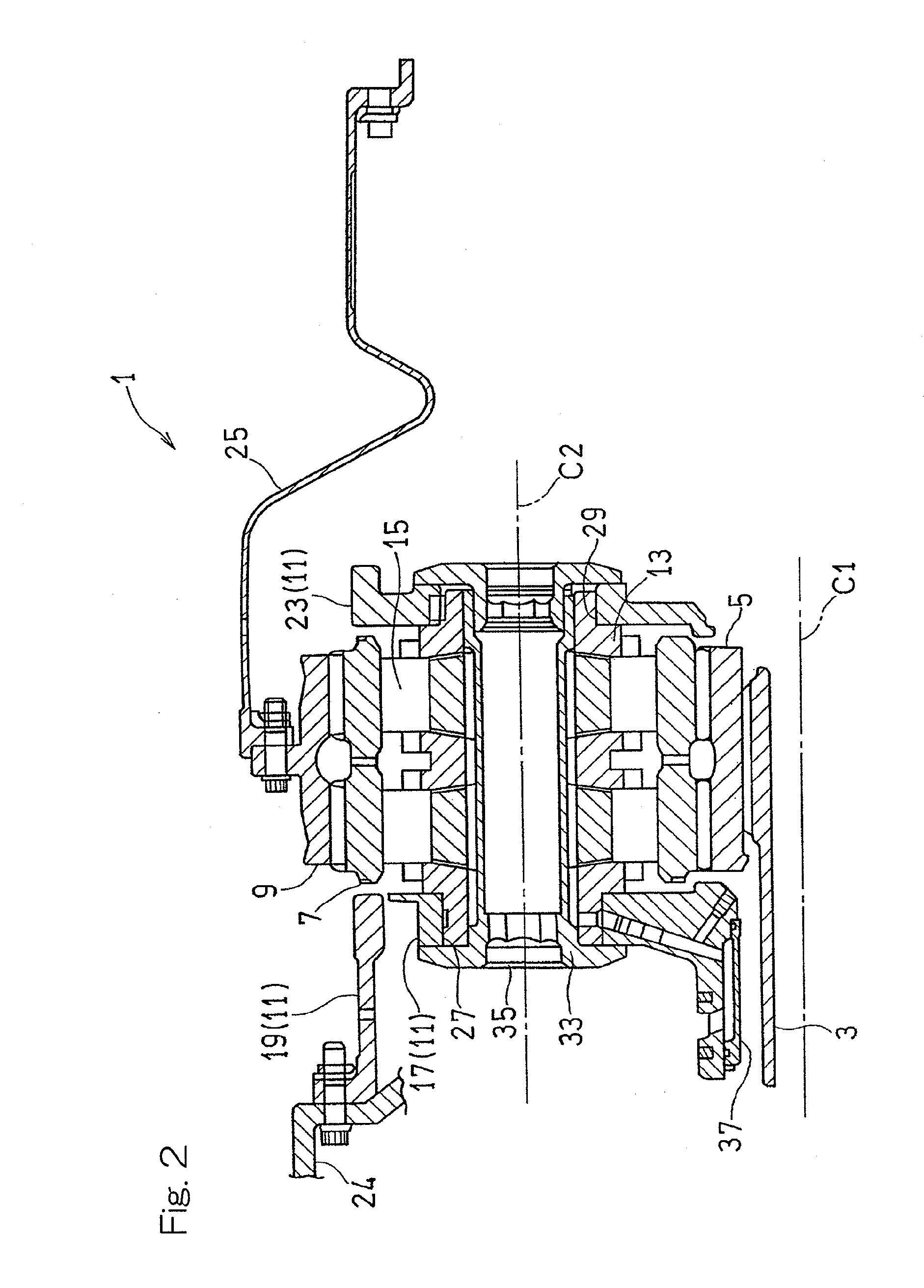
[0029]FIG. 2 is a longitudinal cross-sectional view showing the planetary gear device 1 shown in FIG. 1. As shown in FIG. 2, the planetary gear device 1 is implemented as a double-row gear mechanism, and includes a sun gear 5, a plurality of (in the example described herein, f...


PUM


Abstract

A planetary gear device includes: a sun gear having external teeth; a plurality of planet gears having external teeth and meshed with the sun gear; a ring gear having internal teeth and meshed with the planet gears; and a baffle unit disposed between the planet gears adjacent to each other and configured to collect lubricant oil into a collection chamber. The baffle unit includes: a discharge outlet to discharge a portion of the lubricant oil collected in the collection chamber in an axial direction; and a ring gear oil supply hole to discharge another portion of the lubricant oil in a radially outward direction and supplied to the ring gear, and a weir member separable from the baffle unit and configured to cover a portion of the discharge outlet to reserve the lubricant oil to be discharged through the ring gear oil supply hole.

Description

CROSS REFERENCE TO THE RELATED APPLICATION[0001]This application is a continuation application, under 35 U.S.C. §111(a), of international application No. PCT / JP2013 / 068726, filed Jul. 9, 2013, which claims priority to Japanese patent application No. 2012-183915, filed Aug. 23, 2012, the disclosure of which are incorporated by reference in their entirety into this application.BACKGROUND OF THE INVENTION[0002]1. Field of the Invention[0003]The present invention relates to planetary gear devices mainly used in power transmission mechanisms for aircrafts, and particularly relates to a lubricating structure for such planetary gear devices.[0004]2. Description of Related Art[0005]In recent years, one of the key issues in aircrafts is to reduce fuel consumption from the viewpoint of reduction in operation cost and environmental conservation. Therefore, also for planetary gear devices for use in aircraft engines, reduction in power loss is required.[0006]Conventionally, this type of planeta...

Claims


Application Information

Patent Timeline
Patent Type & Authority Applications(United States)
IPC IPC(8): F16H57/04
CPCF16H57/0409F16H57/0427F16H57/0486B64C27/12F16H1/28
Inventor IMAI, HIDEYUKISATO, MAIKO
Owner KAWASAKI HEAVY IND LTD
Why Eureka
Try Eureka