Packet transfer system and method for high-performance network equipment

a network equipment and packet transfer technology, applied in the field of packet transfer buffer technology, can solve the problems of increasing the number of engines, increasing the types, complexity, destructive power of malicious threats, etc., and achieving the effect of increasing computation time and memory spa

Inactive Publication Date: 2015-06-18
WINS CO LTD
View PDF21 Cites 4 Cited by
  • Summary
  • Abstract
  • Description
  • Claims
  • Application Information

AI Technical Summary

Benefits of technology

[0009]Accordingly, the present disclosure has been made keeping in mind the above problems occurring in the prior art, and the present disclosure provide a packet transfer system for high-performance network equipment, which applies a memory pool to the packet transfer system, thus solving the problem of an increase in computation time and memory space due to a packet copy procedure.
[0010]The present disclosure may shorten the time required to copy data by allowing a plurality of queues to simultaneously refer to a single memory pool in a parallel engine structure.The present disclosure may utilize a scheme for assigning the right to access a memory block to a subsequent memory allocation manager in a series engine structure and swapping an internal memory block with a received memory block.The present disclosure may provide a packet transfer method for high-performance network equipment, which stores packets transferred to an NIC in a memory pool, thus referring to packet information based on memory block addresses.In accordance with an aspect of the present disclosure, there is provided a packet transfer system for high-performance network equipment, including a memory pool processor configured to include therein one or more memory blocks and store packet information input to a Network Interface Controller (NIC), a memory allocation manager configured to control allocation and release of the memory blocks, update information of memory blocks in response to a request of a queue or an engine, and transfer memory block addresses, the queue configured to request a memory block from the memory allocation manager, and transfer a received memory block address to outside of the queue, and the engine configured to receive the memory block address from the queue, and perform a predefined analysis task with reference to packet information. The engine may include a plurality engines, and may be configured to, when the engines have a parallel structure, share memory block addresses of the memory pool, and refer to the memory block addresses.

Problems solved by technology

As the use of the Internet has increased, the types of security threats and the scale of damage attributable to such threats have also increased.
Recently, as threats from the early stage of the Internet such as simple hacking or viruses have developed into various current threats such as worms, spyware, Trojan horses, Distributed Denial of Service (DDoS) attacks, and application vulnerability attacks, the types, complexity, and destructive power of such malicious threats has increased.
However, this scheme is problematic in that the number of engines is increased and a lot of resources are occupied because fixed queues are required for respective engines and the speed of copying is slow, and in that repetitive processing loads occur on equipment requiring high performance.
Since copying is repeatedly performed in proportion to the depth of engines, a problem arises in that the entire performance is deteriorated depending on the complexity of the connected engine structure and processing time.

Method used


Image

  • Packet transfer system and method for high-performance network equipment
  • Packet transfer system and method for high-performance network equipment
  • Packet transfer system and method for high-performance network equipment

Examples


Embodiment Construction

[0022]Hereinafter, embodiments of the present disclosure will be described in detail with reference to the accompanying drawings. Reference now should be made to the elements of drawings, in which the same reference numerals are used throughout the different drawings to designate the same elements. In the following description, detailed descriptions of known elements or functions that may unnecessarily make the gist of the present disclosure obscure will be omitted.

[0023]Detailed configurations and operations of a packet transfer system and method for high-performance network equipment according to the present disclosure will be described in detail with reference to the attached drawings.

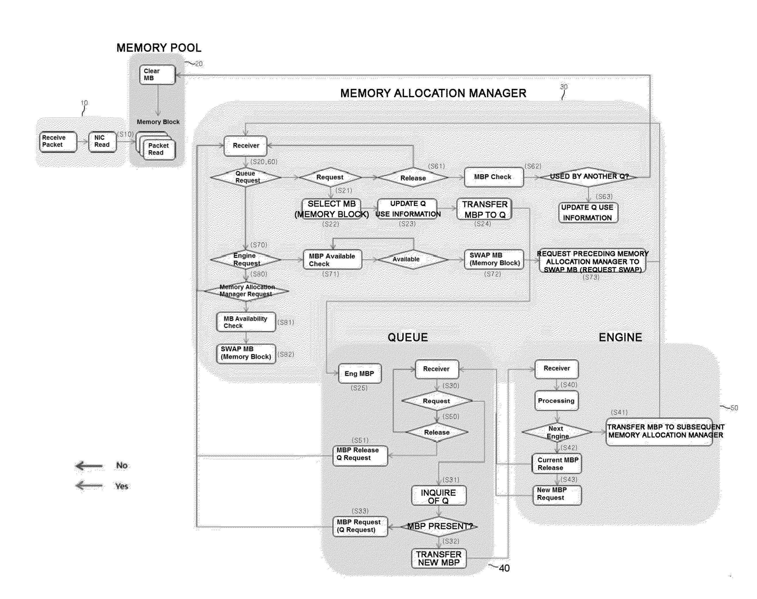
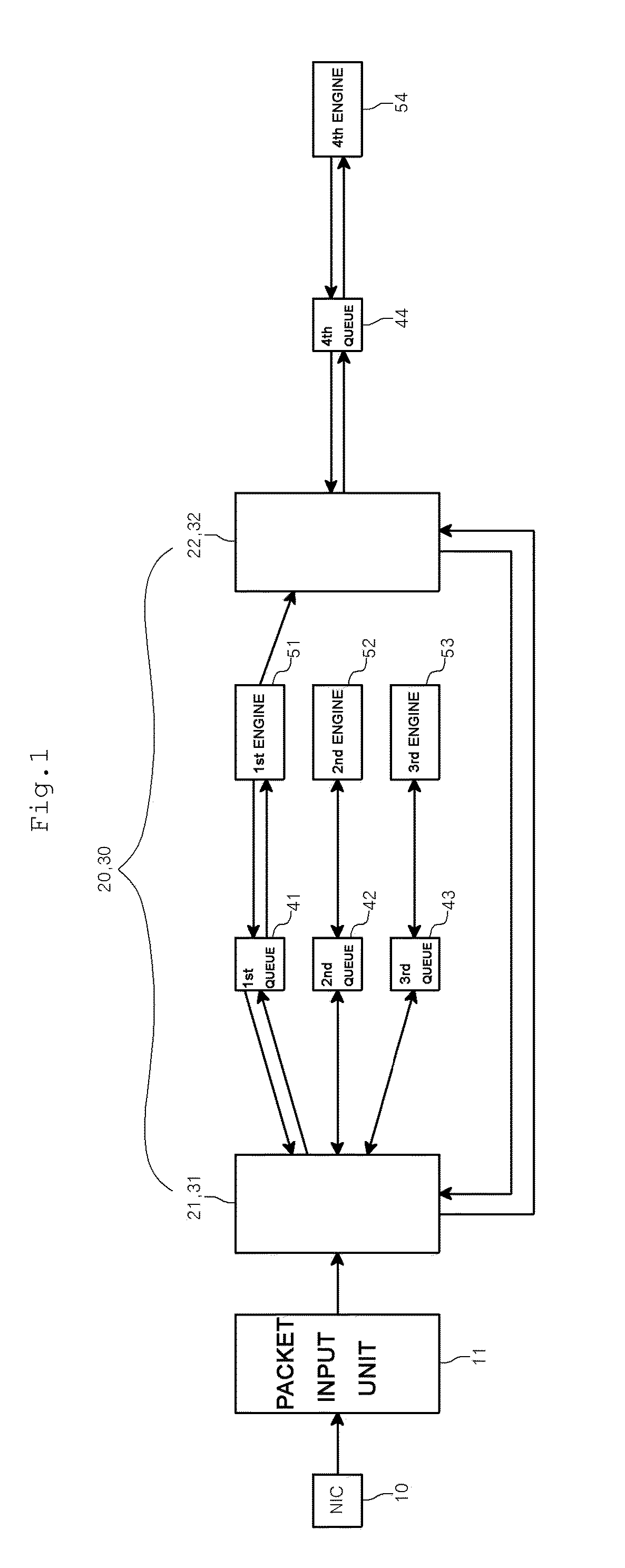
[0024]FIG. 1 is a diagram showing the overall configuration of a packet transfer system for high-performance network equipment according to the present disclosure, wherein the packet transfer system includes a memory pool 20, a memory allocation manager 30, queues 41 to 44, and engines 51 to 54.

[002...


PUM


Abstract

The present disclosure relates to a packet transfer system and method, which can greatly improve the efficiency of a packet transfer scheme using a memory pool technique. The packet transfer system for high-performance network equipment includes a memory pool processor configured to include therein one or more memory blocks and store packet information input to an NIC. A memory allocation manager is configured to control allocation and release of the memory blocks, update information of memory blocks in response to a request of a queue or an engine, and transfer memory block addresses. The queue is configured to request a memory block from the memory allocation manager, and transfer a received memory block address to outside of the queue. The engine is configured to receive the memory block address from the queue, and perform a predefined analysis task with reference to packet information.

Description

CROSS-REFERENCE TO RELATED APPLICATION[0001]This application claims under 35 U.S.C. §119(a) the benefit of Korean Application No. 10-2013-0140916 filed Nov. 19, 2013, which is incorporated herein by reference.TECHNICAL FIELD[0002]The present disclosure relates, in general, to packet transfer buffer technology required when network equipment operating in a transparent mode analyzes packets and, more particularly, to a packet transfer system and method, which can greatly improve the efficiency of a packet transfer scheme using a memory pool technique.BACKGROUND ART[0003]Recently, the Internet has exerted a strong influence in the whole area ranging from the lifestyles of people to the business area of enterprises. In such an environment, it is common for persons to share the details of their lives via a web community, or for persons to enjoy the wireless Internet. As the use of the Internet has increased, the types of security threats and the scale of damage attributable to such threa...

Claims


Application Information

Patent Timeline
Patent Type & Authority Applications(United States)
IPC IPC(8): G06F12/08G06F12/02
CPCG06F12/0813G06F2212/154G06F2212/1044G06F12/023H04L49/9005H04L49/9047G06F13/14G06F12/00G06F13/16G06F13/20
Inventor JIN, YONG SIG
Owner WINS CO LTD
Why Eureka
Try Eureka