Efem

a technology of efem and efem spherical structure, which is applied in the direction of conveyor parts, electric devices, transportation and packaging, etc., can solve the problems of deterioration of yield, corrosion of wiring materials on the wafer surface, corrosion and oxidation, etc., to prevent a decrease in yield, suppress a change in the properties of the wafer surface, and maintain the state of the inside of the wafer transport chamber constant

Active Publication Date: 2015-06-18
SINFONIA TECHNOLOGY CO LTD
View PDF9 Cites 285 Cited by
  • Summary
  • Abstract
  • Description
  • Claims
  • Application Information

AI Technical Summary

Benefits of technology

[0021]Further, in order to replace the inside of the wafer transport chamber to an appropriate gas atmosphere, prevent a decrease in yield caused by adhesion of oxygen gas, moisture and the like to the wafer surface disturbing the wafer processing, and maintain the state of the inside of the wafer transport chamber constant by supplying the flowed amount of gas when a part of the nitrogen in the wafer transport chamber flows out, it is effective to further provide a gas supply means that supplies gas to the wafer transport chamber, and a gas discharge means that discharges the gas from the wafer transport chamber.
[0022]In order to eliminate the molecular contaminants that are generated during processing or the like in the processing apparatus and flowed into the wafer transport chamber, it is desirable to provide a chemical filter in the gas suction port, and to flow the gas in the wafer transport chamber into the gas feedback path through the chemical filter.
[0023]In order to place the wafer transport apparatus and the gas suction port without interfering with each other, and to prevent the particles from floating due to a gasflow turbulence caused by failing to prevent a downward gasflow in the wafer transport chamber, it is preferable to support the wafer transport chamber on the wall of the housing.
[0024]In order to suppress a change in the properties of the wafer surface caused by oxygen, moisture and the likes, and to prevent a decrease in yield, it is preferable to use an inert gas as the gas.
[0025]According to the invention described above, it is possible to provide an EFEM that is able to suppress adhesion of particles to a wafer, and to properly control the properties of the wafer surface, without exposing a wafer during transportation to a change in the surface properties or an atmosphere that causes adhesion of particles, while avoiding an increase in the cost.

Problems solved by technology

In other words, the air atmosphere is likely to permit adhesion of moisture and oxygen to the surface of a substrate, causing corrosion and oxidation.
Further, when a corrosive gas or the like used in the processing apparatus remains on the surface of a wafer, it may cause corrosion of a wiring material on the wafer surface and deterioration of yield.
Further, a corrosion element accelerates a corrosion reaction, and when both moisture and corrosive gas are present, corrosion may develop faster.
Thus, the supplied nitrogen flows out to the wafer transport chamber, causing a problem of an increase in the use amount of nitrogen and an increase in the cost.
However, by simply setting a nitrogen atmosphere upon start of the wafer transportation, the cleanliness in the wafer transport chamber decreases as time passes, there occurs a possibility of adhesion of particles to the wafer surface during transportation in the chamber, and the influence of corrosive gas or the like used in the processing apparatus increases.
Further, when the nitrogen is always supplied to the wafer transport chamber, the use amount of nitrogen increases further, and the cost increase is not solved.
In addition, the above problem arises similarly during transportation of substrates other than a wafer, as long as the transportation is done in an atmosphere different from the processing and storage location.

Method used


Image

  • Efem
  • Efem
  • Efem

Examples


first embodiment

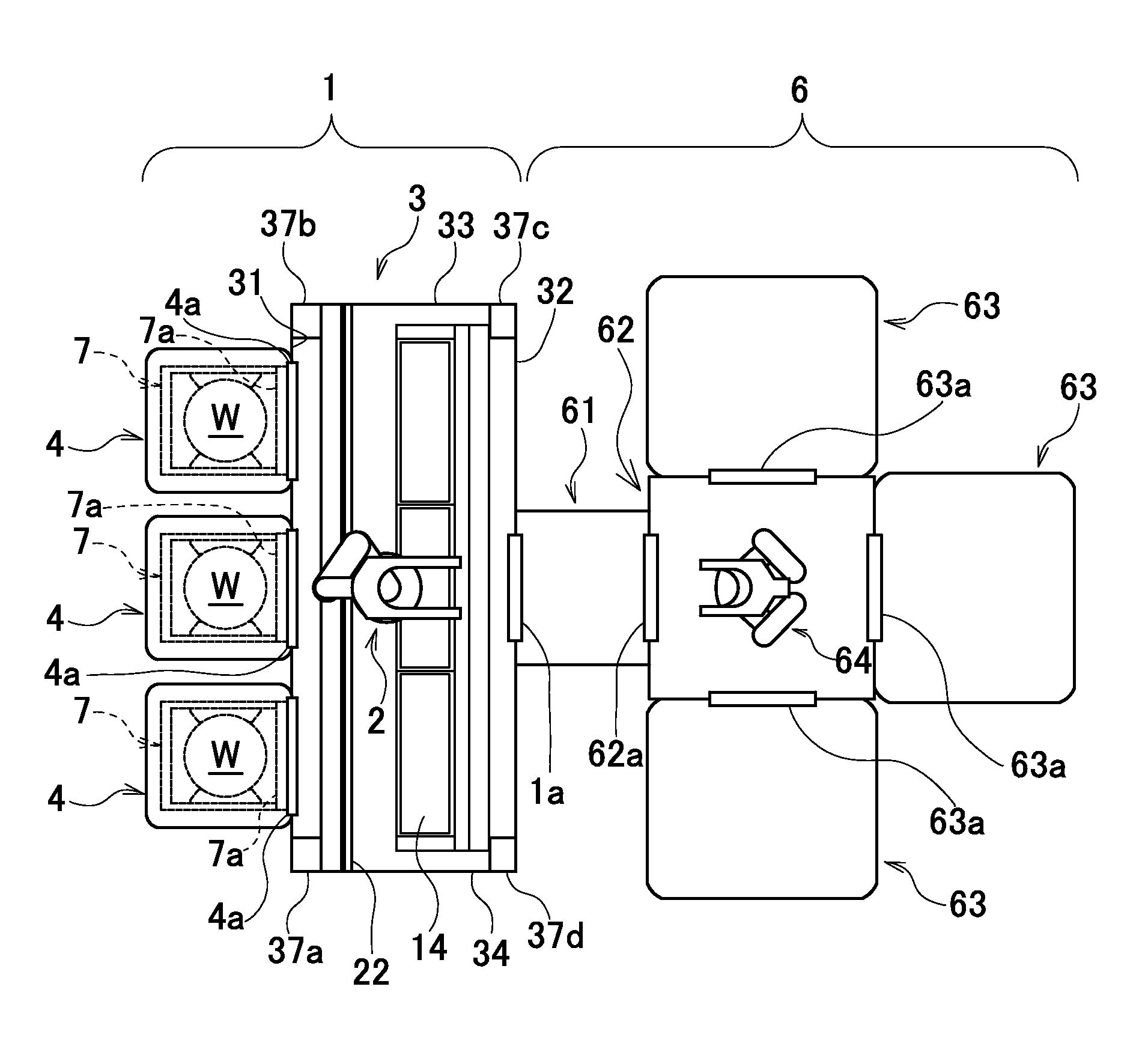
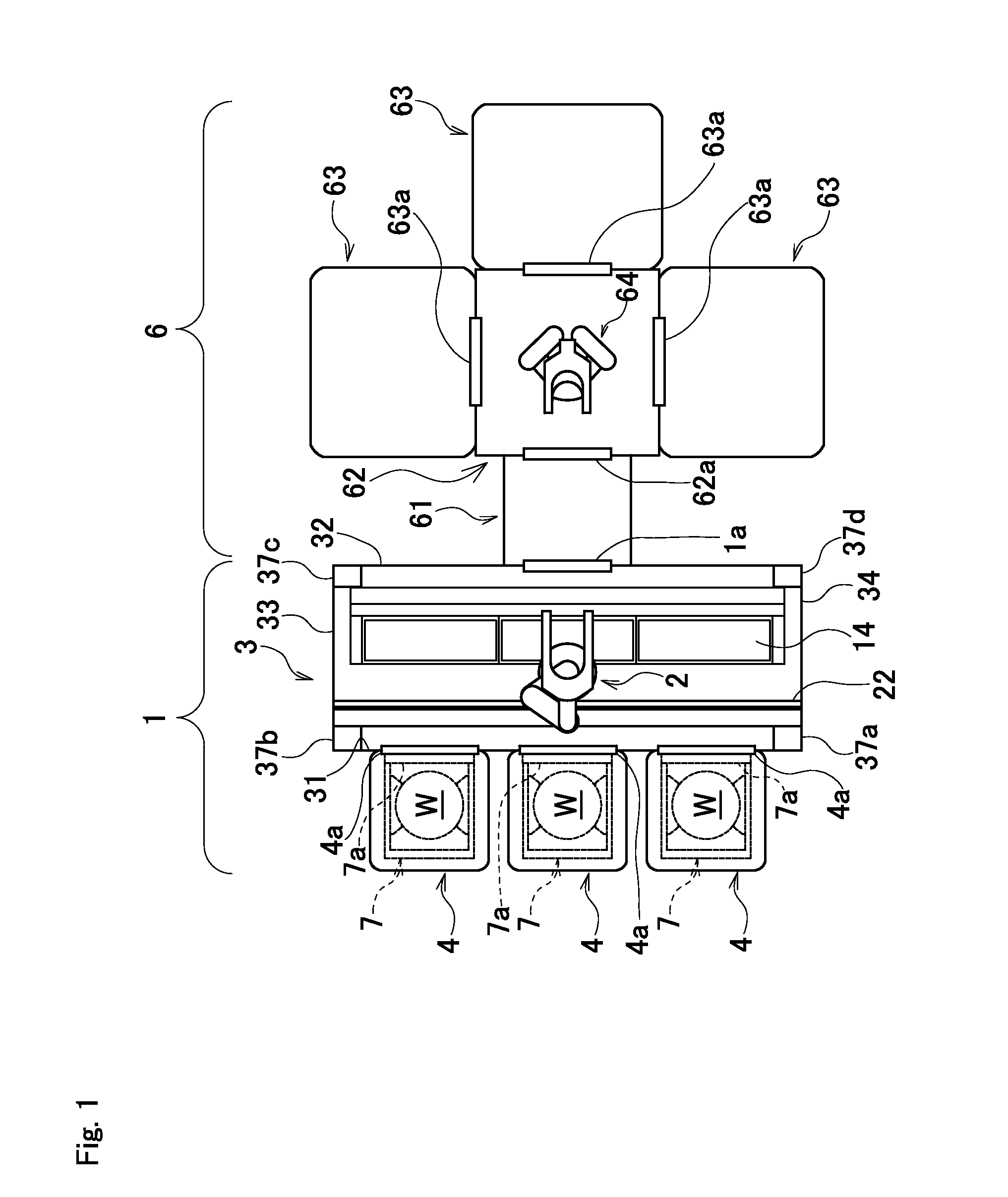
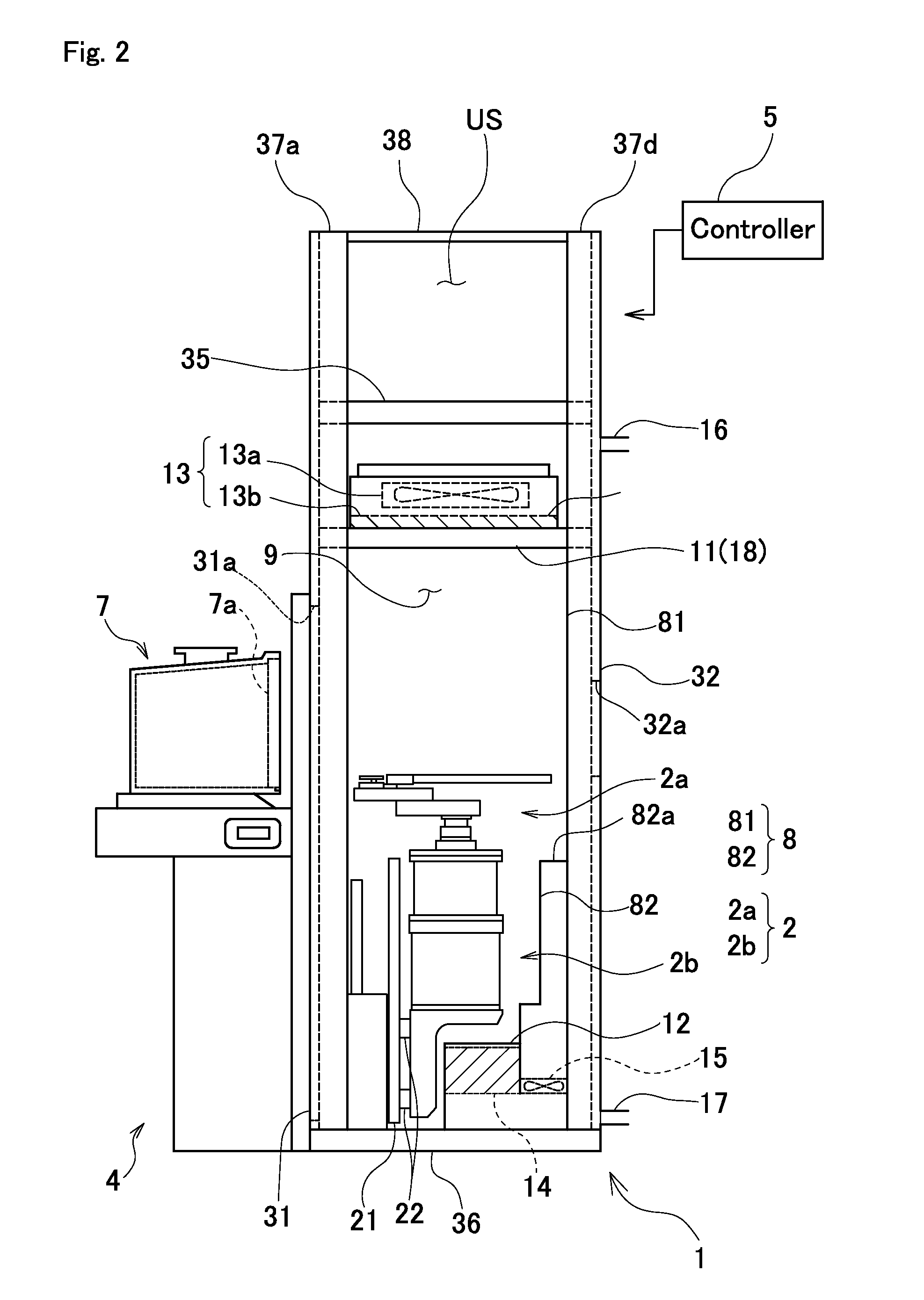
[0072]FIG. 1 is a plan view schematically showing the relationship between an EFEM 1 according to a first embodiment of the invention and a processing apparatus 6 connected thereto, in which a top panel or the like is removed to reveal the interior. FIG. 2 is a side view of the EFEM 1, in which a sidewall is removed to reveal the interior. As shown in FIGS. 1 and 2, the EFEM 1 comprises a wafer transport apparatus 2 that transports a wafer W between predetermined transfer positions, a box-shaped housing 3 that is provided so as to surround the wafer transport apparatus 2, a plurality of load ports 4 (three in the drawing) that is connected to the outside of a wall of the front side (a front wall 31) of the housing 3, and a controller 5.

[0073]In the present application, when viewed from the housing 3, a direction of the side connected to the load port 4 is defined as a front, a direction of a rear wall 32 opposite to the front wall 31 is defined as a rear, and a direction perpendicul...

second embodiment

[0117]A plurality of EFEMs is usually installed in a clean room. Thus, if nitrogen is supplied to each EFEM, the use amount of nitrogen greatly increases. When a device for supplying nitrogen is provided for each EFEM, the installation area of the entire equipment increases, and the cost required for installation and management of the equipment increases.

[0118]Therefore, when a plurality of EFEMs is operated, it is an object of the second embodiment is to provide an EFEM system that suppresses adhesion of particles to a wafer, and realize proper management of the surface properties of a wafer with a simple structure, without exposing a wafer during transport to a change in the surface properties and an atmosphere causing adhesion of particles, thereby reducing the cost and installation area.

[0119]An EFEM system according to the second embodiment is, as shown in FIG. 8, comprises two or more EFEMs 1010 having the same internal volume, that are installed in a clean room, and used when...

third embodiment

[0164]In the first and second embodiment described heretofore, when the volume of the wafer chamber 9, 1011 increases, the cost of the filling gas increases by that amount, and a long time is required to replace the gas. In the third to ninth embodiments, attention is paid to a substrate transport apparatus applied to an EFEM. It is an object of the embodiments to provide a substrate transport apparatus that is configured to suppress adhesion of particles to a substrate, and appropriately manage the properties of a substrate surface, without exposing a substrate during transport to an atmosphere that causes adherence of particles or changes in the surface properties, and an EFEM that is provided with the substrate transport apparatus.

[0165]A substrate transport apparatus applied to an EFEM of the third embodiment is configured as a wafer transport apparatus 2002 that transports a wafer W as a substrate, and forms one of the components of an EFEM 2001 shown in FIG. 13. The EFEM 2001 ...


PUM


Abstract

An EFEM includes a housing 3 that constitutes a wafer transport chamber 9 that is substantially closed by connecting load ports 4 to an opening 31a provided on a wall 31, and connecting a processing apparatus 6; a wafer transport apparatus 2, and transports a wafer between the processing apparatus 6 and the FOUPs 7 mounted on the load ports 4; a gas delivery port 11; a gas suction port 12; a gas feedback path 10; and a FFU 13 that includes a filter 13b that is provided in the gas delivery port 11, and eliminates particles contained in the delivered gas, wherein the gas in the wafer transport chamber 9 is circulated by generating a downward gasflow in the wafer transport chamber 9 and feeding back the gas through the gas feedback path 10.

Description

CROSS-REFERENCE TO RELATED APPLICATIONS[0001]This application claims priority of Japanese Patent Application No. 2013-257817 filed on Dec. 13, 2013, Japanese Patent Application No. 2013-270967 filed on Dec. 27, 2013, Japanese Patent Application No. 2014-017820 filed on Jan. 31, 2014, and Japanese Patent Application No. 2014-017821 filed on Jan. 31, 2014. The contents of the applications are incorporated herein by reference in their entirety.BACKGROUND OF THE INVENTION[0002]1. Field of the Invention[0003]Embodiments of the present invention relate to an EFEM (Equipment Front End Module) capable of circulating gas in a wafer transport chamber without exposing a wafer to the outside air during transportation.[0004]2. Description of the Related Art[0005]Conventionally, production of semiconductors has been carried out by various processing steps performed on a wafer as a substrate. In recent years, circuit miniaturization and high integration of elements have been increasingly promoted....

Claims


Application Information

Patent Timeline
Patent Type & Authority Applications(United States)
IPC IPC(8): H01L21/673H01L21/677
CPCH01L21/67775H01L21/67389H01L21/67115H01L21/67766H01L21/67772H01L21/67778H01L21/67017H01L21/67739
Inventor SEGAWA, MIKIOTANIYAMA, YASUSHINATSUME, MITSUOSUZUKI, ATSUSHIKAWAI, TOSHIHIROSATO, KUNIHIKO
Owner SINFONIA TECHNOLOGY CO LTD
Why Eureka
Try Eureka