

Metallic Material For Electronic Components And Method For Producing Same, And Connector Terminals, Connectors And Electronic Components Using Same
a technology of electronic components and metal materials, applied in the direction of metallic material coating process, printed circuit non-printed electric component association, coupling device connection, etc., to achieve the effect of low degree of whisker formation, low adhesive wear property and high durability
- Summary
- Abstract
- Description
- Claims
- Application Information
AI Technical Summary
Benefits of technology
Problems solved by technology
Method used
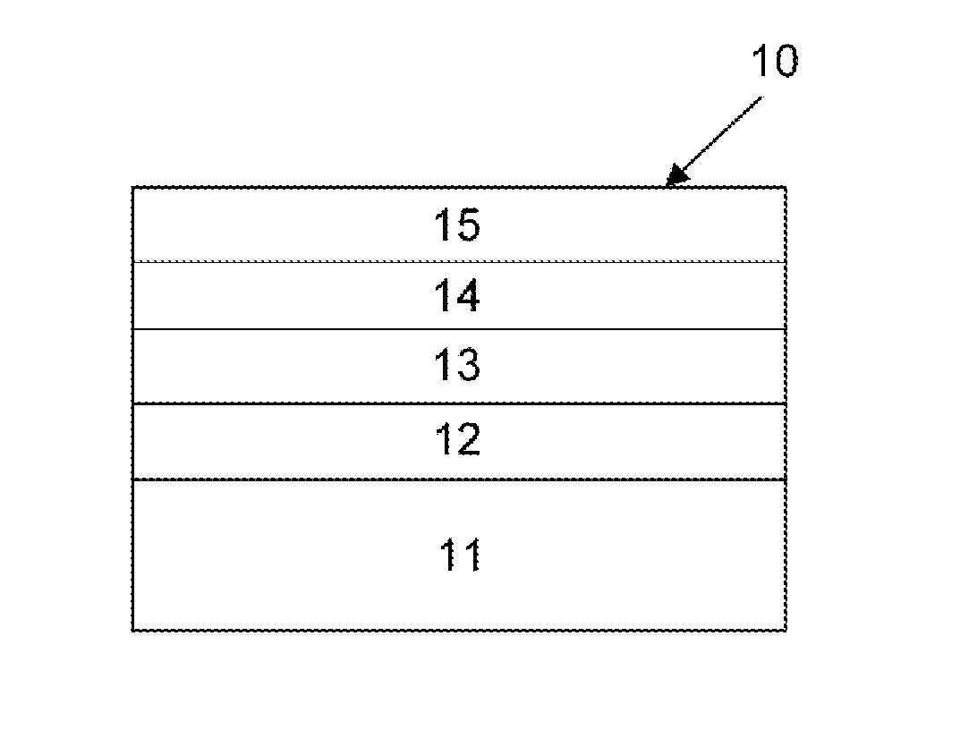
Image

Examples
examples
[0134]Hereinafter, Examples of the present invention, Reference Examples and Comparative Examples are presented together; these Examples and Comparative Examples are provided for better understanding of the present invention, and are not intended to limit the present invention.
[0135]As Examples, Reference Examples and Comparative Examples, under the conditions shown in Table 1, the surface treatment was performed in the sequence of electrolytic degreasing, acid cleaning, first plating, second plating, third plating and heat treatment.
[0136](Materials)[0137](1) Plate: thickness: 0.30 mm, width: 30 mm, component: Cu-30Zn[0138](2) Male terminal: thickness: 0.64 mm, width: 2.3 mm, component: Cu-30Zn[0139](3) Push-in type terminal: Press-fit terminal PCB connector, R800, manufactured by Tokiwa & Co., Inc.
[0140](First Plating Conditions)
[0141](1) Semi-Glossy Ni Plating[0142]Surface treatment method: Electroplating[0143]Plating solution: Ni sulfamate plating solution+saccharin[0144]Plating...
PUM
| Property | Measurement | Unit |
|---|---|---|
| thickness | aaaaa | aaaaa |
| thickness | aaaaa | aaaaa |
| thickness | aaaaa | aaaaa |
Abstract
Description
Claims
Application Information