Wireless communication system and wireless communication method

a wireless communication and wireless communication technology, applied in the field of wireless communication system and wireless communication method, can solve the problems of deteriorating frequency utilization efficiency and throughput performance of the entire system, further degrading performance, and difficult to sufficiently demonstrate the capability of the wireless access point, so as to improve the frequency utilization efficiency and frequency utilization efficiency. the effect of secondary channel frequency use, improved system throughput and improved frequency utilization efficiency

Active Publication Date: 2015-06-18
NIPPON TELEGRAPH & TELEPHONE CORP
View PDF11 Cites 47 Cited by
  • Summary
  • Abstract
  • Description
  • Claims
  • Application Information

AI Technical Summary

Benefits of technology

[0053]In accordance with the present invention, there is an advantageous effect in that frequency in use of secondary channels is improved and system throughput is improved by transmitting data to a plurality of wireless communication stations using orthogonal frequency-division multiple access (OFDMA). In ad

Problems solved by technology

However, because the transmission speed referred to here is a transmission speed on the physical layer and the transmission efficiency in a medium access control (MAC) layer is actually about 50 to 70%, an upper-limit value of the actual throughput is about 30 Mbps and thus this performance is further degraded if the number of wireless communication stations intended to transmit information increases.
As described above, in the system conforming to the IEEE 802.11, it is difficult to sufficiently demon

Method used


Image

  • Wireless communication system and wireless communication method
  • Wireless communication system and wireless communication method
  • Wireless communication system and wireless communication method

Examples


Embodiment Construction

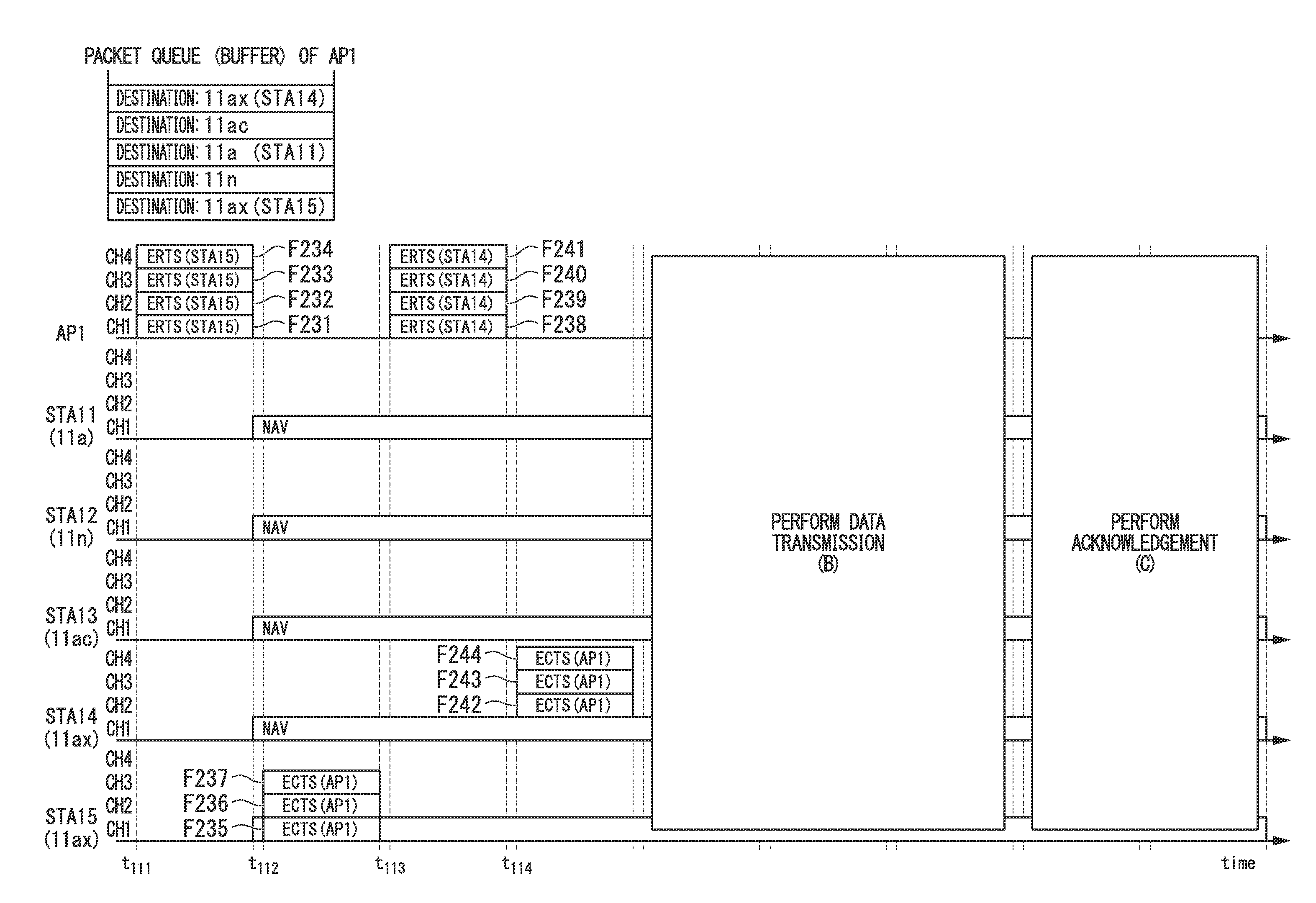
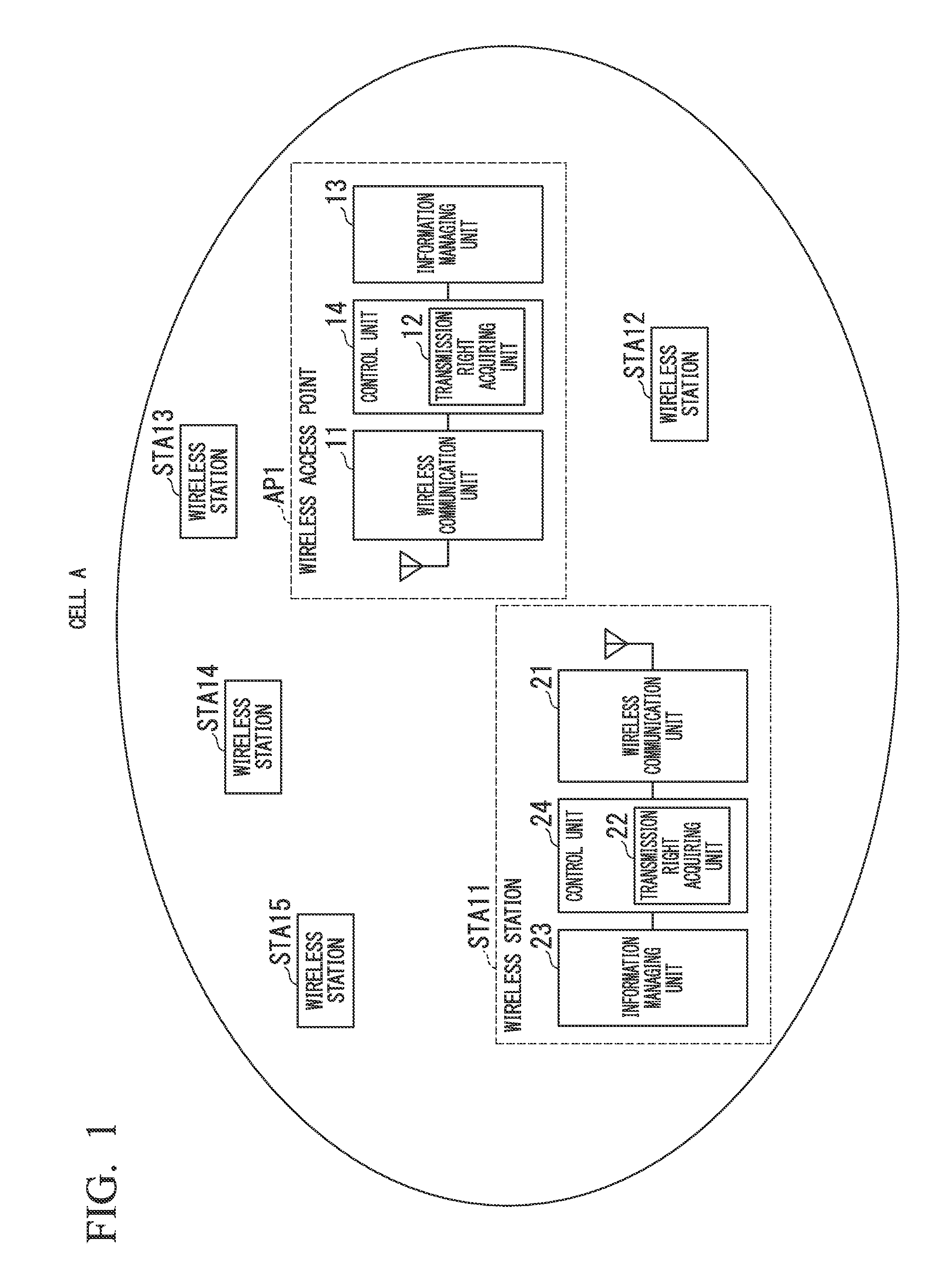
[0129]Hereinafter, a wireless communication system in accordance with an embodiment of the present invention will be described with reference to the drawings. FIG. 1 is a diagram illustrating a block diagram of configurations of a wireless access point and wireless stations and a configuration of a network in the present embodiment. The wireless communication system in the present embodiment is characterized in that a wireless communication station serving as a transmission right acquiring wireless communication station transmits data for a plurality of wireless communication stations on a plurality of channels using orthogonal frequency-division multiple access (OFDMA). A cell A of the wireless communication system illustrated in FIG. 1 includes a wireless access point AP1, which is a wireless communication station, and five wireless stations STA11 to STA15. It is assumed that the wireless access point AP1 and the wireless stations STA14 and STA15 are wireless communication station...


PUM


Abstract

In order to provide a wireless communication system capable of improving the throughput of wireless communication by effectively using frequency resources, in a wireless communication system in which a first wireless access point which communicates with one or more wireless stations within a first cell by orthogonal frequency-division multiple access and a second wireless access point which is capable of performing carrier sensing with the first wireless access point and communicates with one or more wireless stations within a second cell by the orthogonal frequency-division multiple access operate in cooperation with each other, the first wireless access point includes a transmission opportunity acquiring unit which acquires a transmission opportunity when data to be transmitted is generated; and a transmitting unit of permission for use which transmits permission for use of channels which are not scheduled to use within the first cell, to the second wireless access point in a period in which the transmission opportunity is acquired, and the second wireless access point includes a communication unit which communicates with the wireless station within the second cell via the channel in which the permission for use is acquired from the first wireless access point.

Description

TECHNICAL FIELD[0001]The present invention relates to a wireless communication system and a wireless communication method for performing wireless communication while effectively using frequency resources.[0002]Priority is claimed on Japanese Patent Applications (Patent Application Nos. 2012-160843 and 2012-160844), the contents of which are incorporated herein by reference.BACKGROUND ART[0003]In recently years, the spread of the IEEE 802.11g standard, the IEEE 802.11a standard, or the like for high-speed wireless access systems using a 2.4 GHz band or a 5 GHz band has been remarkable. In these systems, a physical layer transmission speed of a maximum of 54 Mbps is realized using an orthogonal frequency division multiplexing (OFDM) modulation scheme, which is technology for stabilizing performance in a multipath fading environment (e.g., see Non-Patent Documents 1 and 4).[0004]However, because the transmission speed referred to here is a transmission speed on the physical layer and t...

Claims


Application Information

Patent Timeline
IPC IPC(8): H04L5/00H04W72/04H04J11/00
CPCH04L5/0007H04J11/005H04L5/0032H04W72/0426H04J11/0063H04W74/0816H04W16/14H04W74/0808H04L5/0023H04L5/0087H04L5/0098H04L27/0006H04L5/0035H04L1/1854H04J11/0053H04W72/27H04J1/00H04J11/00H04L1/18H04W28/16
Inventor ABEYSEKERA, HIRANTHA SITHIRAINOUE, YASUHIKOASAI, YUSUKESHINOHARA, SHOKOICHIKAWA, TAKEOMIZOGUCHI, MASATO
Owner NIPPON TELEGRAPH & TELEPHONE CORP
Why Eureka
Try Eureka