
Separating film and method

a technology of film and film layer, applied in the field of film separation, can solve the problems of unavoidable manufacturing-related tolerances, unforeseeable reduction in service life, and components made of fiber-reinforced plastics, and achieve the effect of reducing the gap dimension

Active Publication Date: 2015-06-25
AIRBUS OPERATIONS GMBH
View PDF7 Cites 5 Cited by
  • Summary
  • Abstract
  • Description
  • Claims
  • Application Information

AI Technical Summary

Benefits of technology

The invention aims to reduce the joining time of components that have tolerances by using a curable levelling compound to compensate for the differences. An anti-adhesion layer is provided with a heating layer to speed up the hardening process of the compound, which results in faster manufacturing and energy usage. The components can be made of carbon fiber-reinforced plastics or metallic materials. A separating film is used that includes an anti-adhesion layer and a heating layer to improve position fixation of the components. The heating layer can also have an adhesive layer for reliable position fixation.

Problems solved by technology

Components made of fiber-reinforced plastics, e.g., carbon fiber-reinforced plastic (“CFRP”), glass fiber-reinforced plastics (GFP), plastics reinforced with Aramid® fibers or suchlike, generally exhibit unavoidable manufacturing-related tolerances which can arise, for example through incalculable dimension changes during the hardening process of the components.
If, without prior reduction in the gap dimension in the joining zone the components are joined with a still admissible stress, an unforeseeable reduction in the service life can occur, which is not tolerable in aviation applications.
However, due to the indirect effect of these heat sources, such procedures require a disproportionate use of energy and bring about an unwarrantable increase in the manufacturing cost as a result of the need for additional production equipment, e.g., stands, holders, clamping devices or frames.

Method used


Image

  • Separating film and method
  • Separating film and method
  • Separating film and method

Examples


Embodiment Construction

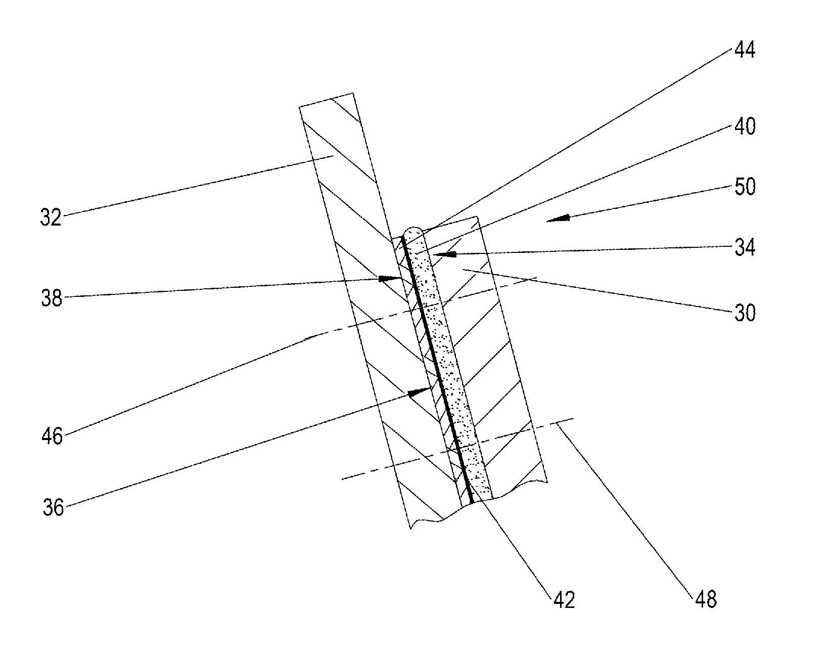
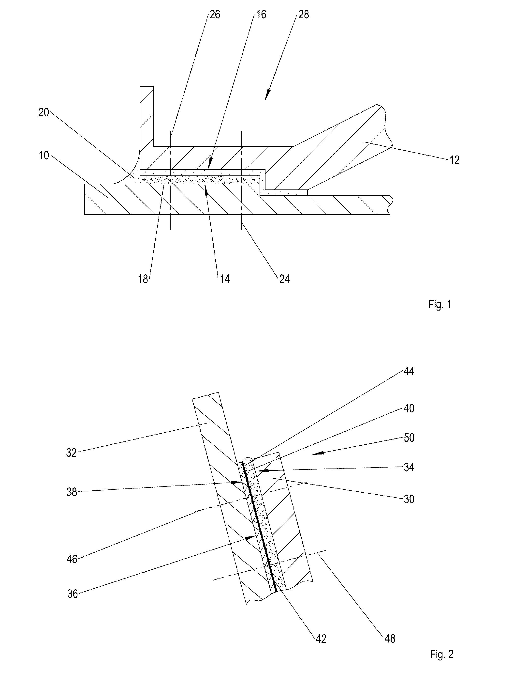
[0030]FIG. 1 shows a schematic cross-section of pressure-tight joint between two components using a curable levelling compound for tolerance compensation as is widely found in aircraft manufacturing.

[0031]A first component 10 and a second component 12 each have a joining zone 14, 16, which face each other and run in parallel at a distance from one another. The necessary vertical tolerance compensation between the two components 10, 12 takes place, here only as an example, through a curable levelling compound 18 applied in the region of the joining zone 14 of the first component 10. Alternatively, the curable levelling compound 18 can also be applied in the region of the joining zone 16 of the second component 12. Optional pressure-tight sealing between the components 10, 12 takes place by means of a preferably permanently elastically hardening sealing mass 20. The components 10, 12 thus positioned with regard to each other are completed with structural connection means 24, 26 such a...


PUM

PropertyMeasurementUnit
Fractionaaaaaaaaaa
Thicknessaaaaaaaaaa
Thicknessaaaaaaaaaa

Abstract

A separating film with an anti-adhesion layer for preventing an adhesive connection between a thermally curable levelling compound, applied in the region of a joining zone of a first component, and a joining zone of a second component to be joined to the first component. The anti-adhesion layer is provided, at least in parts, with a heating layer. As a result of the actively electrically heatable heating layer of the separating film, which is an integral part of the separating film, the processing time for joining two components, which are subject to tolerances, using a thermally curable levelling compound (known as liquid shimming), can be reduced by at least 40% compared with the conventional process.

Description

CROSS-REFERENCES TO RELATED APPLICATIONS[0001]This application claims the benefit of the German patent application No. 10 2013 114 574.4 filed on Dec. 19, 2013, the entire disclosures of which are incorporated herein by way of reference.BACKGROUND OF THE INVENTION[0002]The invention initially relates to a separating film with an anti-adhesion layer for preventing an adhesive connection between a thermally curable levelling compound applied in the region of a joining zone of a first component and a joining zone of a second component to be joined to the first component. The subject matter of the invention is also a method of joining two components that are subject to tolerances.[0003]Components made of fiber-reinforced plastics, e.g., carbon fiber-reinforced plastic (“CFRP”), glass fiber-reinforced plastics (GFP), plastics reinforced with Aramid® fibers or suchlike, generally exhibit unavoidable manufacturing-related tolerances which can arise, for example through incalculable dimensi...

Claims


Application Information

Patent Timeline
IPC IPC(8): B32B37/12B32B27/30B32B5/02B32B37/24B32B38/10
CPCB32B37/1284B32B37/24B32B38/10B32B5/024B32B2250/02B32B27/30B32B2037/243B32B2605/18B32B5/026B29C65/562B29C66/0042B29C66/02B29C66/12821B29C66/1284B29C66/131B29C66/53B29C66/54B29C66/721B29C66/7212B29C66/742B32B7/12B32B15/02B32B15/08B32B27/20B32B27/322B32B2262/106B32B2307/202B29C65/7826B29C66/02245Y10T156/10Y10T428/31544Y10T442/3976Y10T442/40B29K2307/04B29K2309/08B29K2277/10
Inventor MALKE, CHRISTIANSCHILDT, RAINER
Owner AIRBUS OPERATIONS GMBH
Learn More