
Method for forming a pouch

a technology of a pouch and a pouch body, which is applied in the field of forming a pouch, can solve the problems of cumbersome and difficult operation of the dispenser or gun, affecting the operation efficiency of the dispensing device, and requiring significant hand strength

Active Publication Date: 2015-06-25
HENKEL IP & HOLDING GMBH
View PDF12 Cites 5 Cited by
  • Summary
  • Abstract
  • Description
  • Claims
  • Application Information

AI Technical Summary

Benefits of technology

The pouch design allows for efficient, one-handed dispensing of viscous materials with precise control, minimizing waste and environmental impact by using a foldable and compressible structure that ensures complete use of the material without the need for additional dispensing devices.

Problems solved by technology

There are difficulties associated with these containers.
The dispenser or gun may be cumbersome and difficult to operate, especially in constrained spaces in buildings under construction.
Also, the dispensing device may require significant hand strength, which adds challenge to dispensing and laying a clean sealant bead.
Discarding is uneconomical and may be highly undesirable for environmental reasons.
At present, there is no known recycling available for the wide variety of sealant compositions available on the market.
And unless the container is correctly reclosed, the residual material will be lost.
But these caps are fragile pieces that are easily split or otherwise damaged from over-tightening.
Or, the snap-fit bead and groove may not provide an enduring reclose fit until the time when the tube is next required for a caulk job.
But frequently, these solutions do not prevent content hardening for more than a short period of time.
But, oftentimes these mechanisms do not work because the packets rupture or the packets contain enough air to dry the tube contents.
And, a foil or wrap can not be closely and tightly wrapped around the tube and nozzle without air gap.

Method used


Image

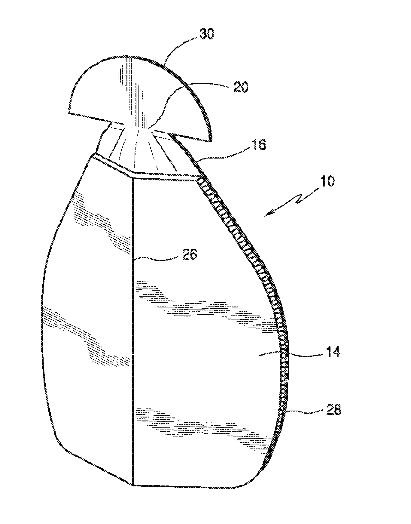
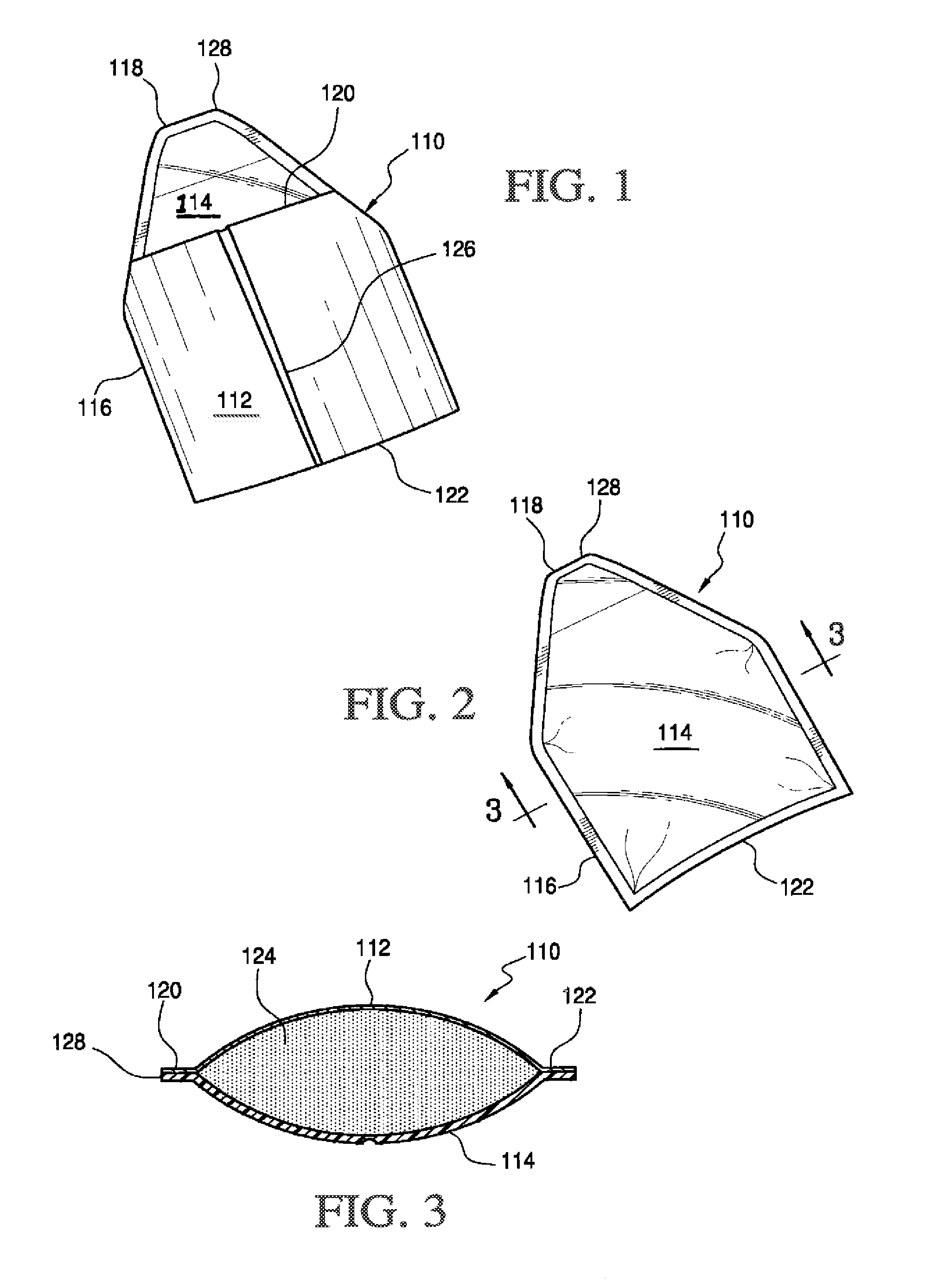
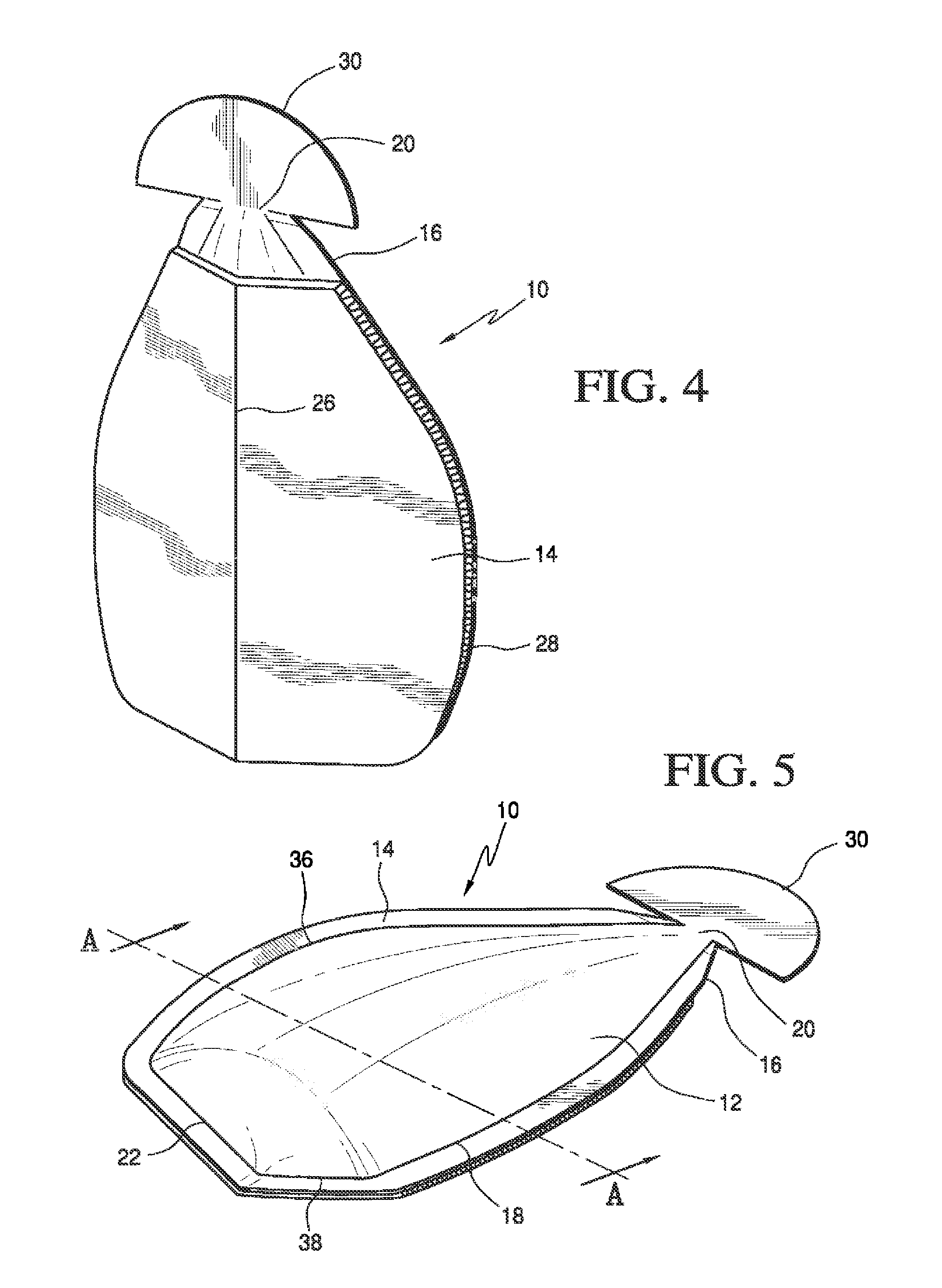
  • Method for forming a pouch
  • Method for forming a pouch
  • Method for forming a pouch

Examples


example 1

[0038]Packet samples are evaluated to establish a design for dispensing a viscous material.

[0039]The samples are constructed from clear polypropylene Ziploc® packets, thin (<1 mm) black polypropylene and polyethylene sheet and acrylic thin film (<1 mm). The sheet materials are formed and heat sealed into packet shapes by first cutting oversized top and bottom rectangular shapes with triangular ends and heat sealing the pieces together with the triangular ends at one side to form a nozzle. Some of the packets are formed with gussets. The gussets are formed by folding the film at the packet sides and bottom.

[0040]Excess material is cut away from the packet after forming. Each packet is filled with material and then heat sealed to form an enclosure. The packets vary in length from about 4 cm to 20 cm, in width from about 2 cm to 15 cm and in thickness (filled with material) from about 0.5 cm to 2 cm. The packets are filled with acrylic caulk or silicone sealant.

[0041]A panel of evaluat...

example 2

[0046]A resulting design was functionally tested by others that represented a consumer panel. Ten packets of the design were distributed among 6 persons of the panel. Each person was instructed to express material from a packet according to a procedure of manually pressing the packet with one hand with an index finger along the crease to fold the packet longitudinally to express the sealant from the packet nozzle.

[0047]A jury of designers observed the expressing procedures and noted the panel's comments. The consumer panel responses were filmed to capture use of the packet and comments

[0048]The panel approved the proposed design. The following panel comments on the design were recorded: “This is really nice! I'm digging this.”“I think that's kind of amazing. I can only say good things about it.”“Super easy to use. I love the bead that it gave me. It feels like I have a lot of control.”“I like this already, and tell you why. Because you can really manipulate the pressure. You can do ...

example 3

[0050]This EXAMPLE describes a series of iterative evaluations of packet samples to determine a best more rigid material.

[0051]First, a range of materials including a paperboard, plastic sheet and corrugated fiberboard were evaluated for output performance. Sample paperboard thickness was varied from approximately 0.010″ to 0.100″; a high density polyethylene sheet (HDPE) was varied in thickness from approximately 0.005″ to 0.100″; and a corrugated fiberboard corrugation was varied from B flute to N flute.

[0052]User ratings determined that a paperboard with a thickness less than approximately 0.080″ did not have sufficient stiffness for acceptable dispensing and “ease of use.” A thicker paperboard gave improved performance results but was rated unacceptable because of bulky feel. Thinner HDPE samples below 0.040″ in thickness, were rated unacceptable because of insufficient stiffness. Thicker HDPE samples showed improved performance but increased cost.

[0053]Performance for corrugate...


PUM

PropertyMeasurementUnit
thicknessaaaaaaaaaa
thicknessaaaaaaaaaa
thicknessaaaaaaaaaa

Abstract

A method of forming and filling a pouch, comprises forming opposing walls of a film; sealing the opposing walls of film together to form at least one pouch; filling an interior section of the at least one pouch through an opening in an upper portion of the at least one pouch with a flowable material; forming a top sealed expressing-shaped region to close the opening in the at least one pouch; and cradling the pouch with a foldable flat that is more rigid than the pouch that can be folded or rolled to compress the pouch to express the flowable material through the expressing shaped region.

Description

[0001]This application is a continuation-in-part of U.S. application Ser. No. 11 / 613,661, filed Dec. 20, 2006, which is incorporated herein by reference in its entirety and this application is a continuation-in-part of U.S. application Ser. No. 12 / 200,376, filed Aug. 28, 2008 which claims benefit of provisional application 60 / 969,232 filed Aug. 31, 2007, which are incorporated herein by reference in their entirety and this application is a continuation-in-part of U.S. application Ser. No. 12 / 236,555, filed Sep. 24, 2008.BACKGROUND OF THE INVENTION[0002]The invention relates to a method of forming a pouch for dispensing viscous material.[0003]Viscous materials can include sealant, mastic, adhesive, glazing, caulk, grout and glue compositions. Typically, such viscous materials are packaged, stored or commercialized in cardboard containers or plastic dispensers or cartridges that are adapted to be loaded into an extrusion device such as a caulking gun. These viscous materials include s...

Claims


Application Information

Patent Timeline
Patent Type & Authority Applications(United States)
IPC IPC(8): B65B43/02B65B61/20B65B51/02B65B61/24B65D75/58B65D75/30
CPCB65B43/02B65D75/5811B65B61/202B65B51/02B65B61/24B65D75/30B65B69/005B65D75/28B05C17/00583B65B3/02B65B7/02B65D35/10B65D35/28
Inventor SHARP, PHILLIP NEALNEWMAN, SWENTHOMSEN, DAVID C.MOOY, ANITA G.
Owner HENKEL IP & HOLDING GMBH
Learn More