Detecting a pitch angle adjustment fault

a technology for adjusting faults and rotor blades, which is applied in the direction of instruments, digital computer details, machines/engines, etc., can solve problems such as failure of one or more controllers, affecting the adjustment of rotor blade pitch angles, and affecting the accuracy of rotor blade adjustment, so as to reduce the risk of damage to components, improve the method, and increase the robustness

Active Publication Date: 2015-06-25
SIEMENS GAMESA RENEWABLE ENERGY AS
View PDF9 Cites 23 Cited by
  • Summary
  • Abstract
  • Description
  • Claims
  • Application Information

AI Technical Summary

Benefits of technology

[0019]Taking the average or the maximum rotor blade pitch angle speed among at least two rotor blades of the wind turbine may even detect a failure involving only one of the rotor blades, thereby improving the method (increasing robustness) and reducing a risk of damaging components of the wind turbine. For example, even if only one rotor blade is affected from a rotor blade pitch angle adjustment fault or failure, the maximum of the rotor blade pitch angle speed among all rotor blades of the wind turbine may correspond to the rotor blade pitch angle speed of the rotor blade affected by the servo system fault. Thus, also such a servo system fault affecting only one or only few (but not all) rotor blades may be detected. Also a servo fault on all rotor blades may be detected. If all blades are e.g. stuck at a constant pitch angle then both the individual or average pitch speed may deviate from the expected pitch speed and trigger indicating the fault.
[0020]An advantage of calculating the speed as the mean speed of multiple (or all) blades could be to reduce noise (from the derivative of the angle measurement) or allow for some individual pitch control (IPC) where each blade may have an additional cyclic pitch angle added to the collective pitch signal for the PI controller. Taking the average may remove some of the contribution on the added IPC signal, that would otherwise be detected at as a unexpected pitch speed deviation.

Problems solved by technology

A cause of the deviation between the actual rotor blade pitch angle speed and the intended or desired rotor blade pitch angle speed may be a failure of a pitch servo system which, via a controller and / or a hydraulic pitch angle adjustment system, may be responsible for setting or adjusting the rotor blade pitch angles.
The failure of the pitch servo system may involve a failure of one or more controllers of the pitch servo system and / or a failure of some mechanical portion or some hydraulic portion of the pitch servo system.
For example, a hydraulic line or tubing may be damaged such that a pressure in the hydraulic system may be smaller than an intended pressure thereby hampering or even prohibiting the adjustment of the rotor blade pitch angles via the hydraulic system in a proper manner.

Method used


Image

  • Detecting a pitch angle adjustment fault
  • Detecting a pitch angle adjustment fault
  • Detecting a pitch angle adjustment fault

Examples


Embodiment Construction

[0072]The illustration in the drawings is in schematic form. It is noted that in different figures, similar or identical elements are provided with the same reference signs or with reference signs, which are different from the corresponding reference signs only within the first digit.

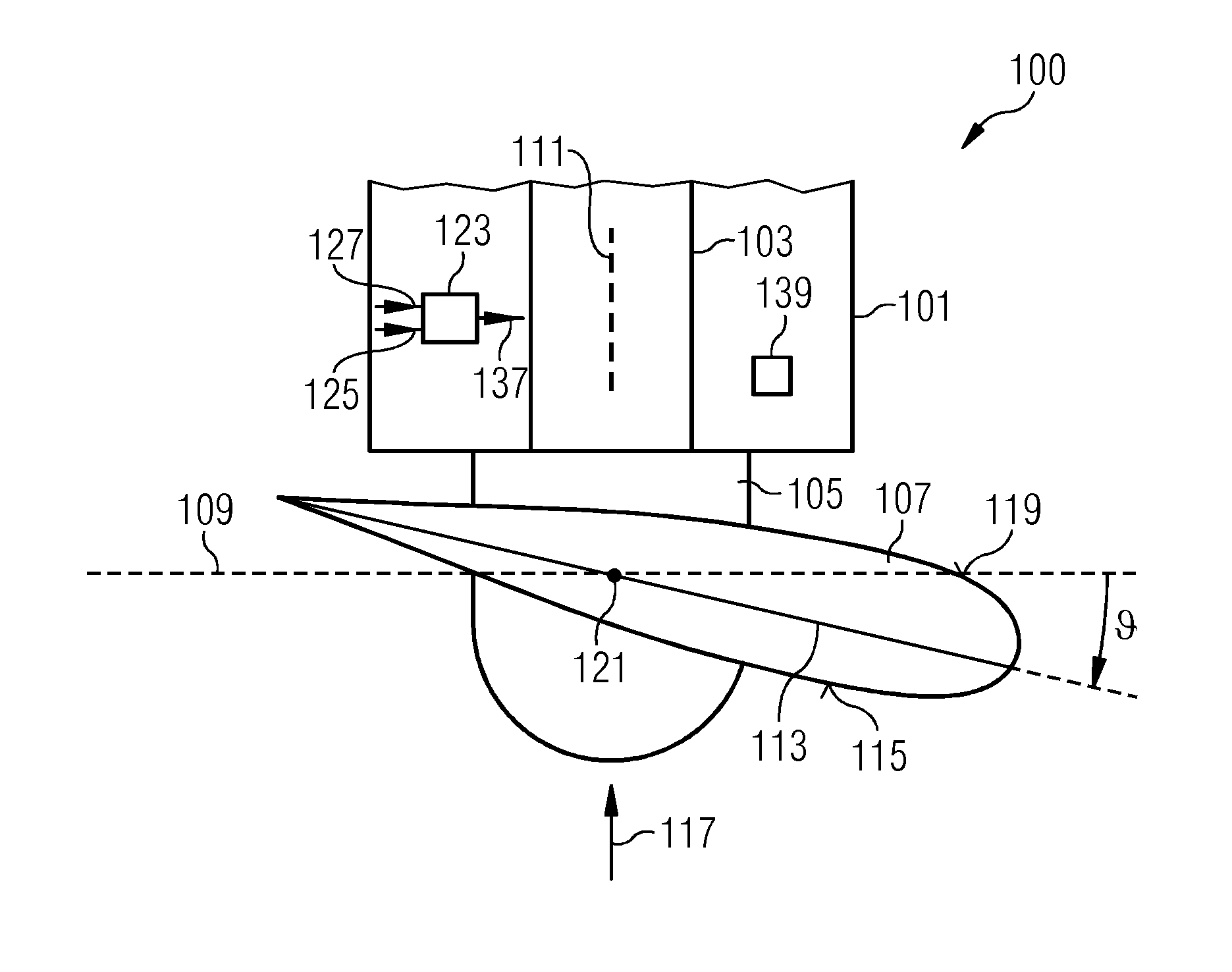
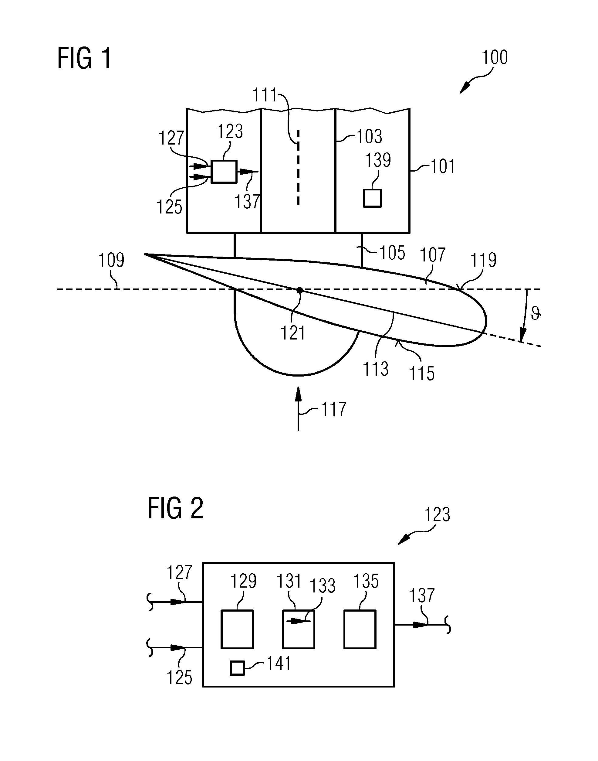
[0073]The wind turbine 100 illustrated in a top view in FIG. 1 comprises a nacelle 101 in which a rotor shaft 103 is supported in a not illustrated bearing and can rotate within the nacelle 101. To the rotor shaft 103, a hub 105 is connected to which one or more rotor blades 107 are attached, wherein only one rotor blade 107 is illustrated in FIG. 1. The rotor blade 107 rotates in a rotation plane 109 which is perpendicular to an axis 111 of the rotor shaft 103. The rotor blade 107 has a particular cross sectional profile or airfoil having a, relative to a chord line 113, thinner side 115 facing the wind 117 and having a thicker side 119 directed away from the wind 117. The rotor blade 107 can be rotate...


PUM


Abstract

A method for detecting a rotor blade pitch angle adjustment fault of a rotor blade of a wind turbine is provided, the method includes measuring a rotor blade pitch angle speed; predicting, based on an actual rotor speed, a rotor blade pitch angle speed; indicating a fault, if a first criterion is satisfied, wherein the first criterion is satisfied, if deviation between the measured rotor blade pitch angle speed and the predicted rotor blade pitch angle speed exceeds a speed threshold.

Description

CROSS REFERENCE TO RELATED APPLICATIONS[0001]This application claims the benefit of European Application No. EP13198987 filed Dec. 20, 2013, incorporated by reference herein in its entirety.FIELD OF INVENTION[0002]The present invention relates to a method and to an arrangement for detecting a rotor blade pitch angle adjustment fault of a rotor blade of a wind turbine.ART BACKGROUND[0003]A wind turbine comprises a wind turbine tower, a nacelle mounted on top of the wind turbine tower, wherein a shaft is supported in a bearing and can rotate within the nacelle. The wind turbine shaft has one or more wind turbine blades connected to it and drives an electrical generator. The rotor blades may be turned or rotated or adjusted around their longitudinal axis, in order to adjust a rotor blade pitch angle, being an angle between a cord line of the rotor blade and a rotor plane being a plane perpendicular to the axis of the shaft which is driven by the rotor blades. For example, when the roto...

Claims


Application Information

Patent Timeline
Patent Type & Authority Applications(United States)
IPC IPC(8): F03D11/00F03D7/04F03D7/02
CPCF03D11/0091F03D7/044F03D7/0224F05B2260/821F05B2260/83F05B2270/328F03D7/024F05B2270/309F03D17/00Y02E10/72
Inventor EGEDAL, PERHOEGH, GUSTAVKALLESOEE, BJARNE SKOVMOSE
Owner SIEMENS GAMESA RENEWABLE ENERGY AS
Why Eureka
Try Eureka