

Electric power converter
a technology of electric power converter and converter, which is applied in the direction of process and machine control, battery/fuel cell control arrangement, instruments, etc., can solve the problems of increasing circuit size and increasing cost, and achieve the effect of reducing rippl
- Summary
- Abstract
- Description
- Claims
- Application Information
AI Technical Summary
Benefits of technology
Problems solved by technology
Method used
Image

Examples
embodiments
[0034]Hereinafter, embodiments will be described with reference to the drawings. It is to be noted that, in all of the drawings, identical or corresponding parts are given identical reference characters, and duplicate descriptions thereof may be omitted.
[0035]In addition, the embodiments described hereinafter illustrate comprehensive or specific examples. Numerical values, shapes, materials, components, arrangement of components, connection modes, waveforms, and so forth indicated in the embodiments hereinafter are examples, and are not intended to limit the present disclosure. Furthermore, among components described in the embodiments hereinafter, components that are not described in an independent claim expressing the broadest concept are described as optional components.
[Configuration of Electric Power Converter 100]
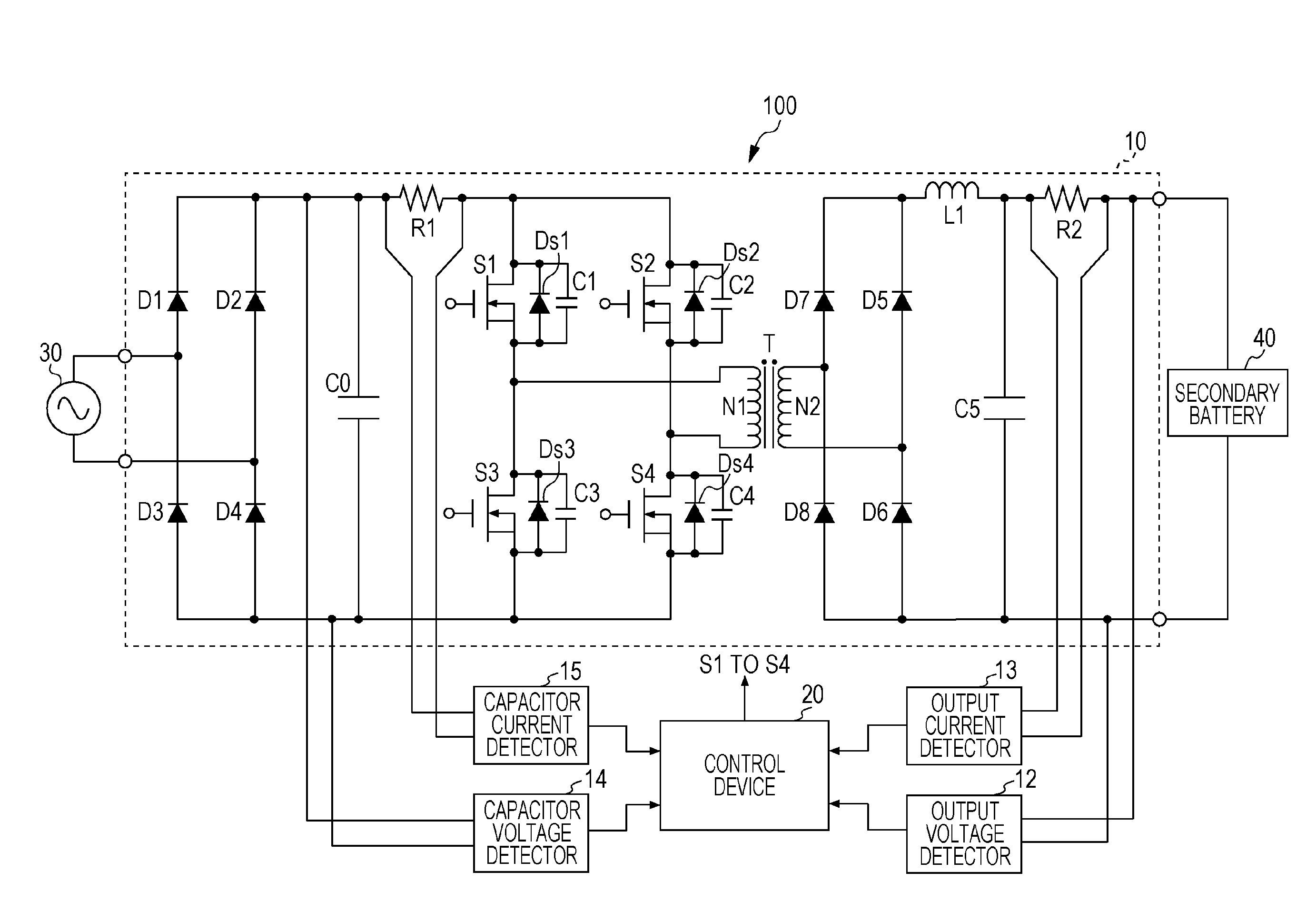
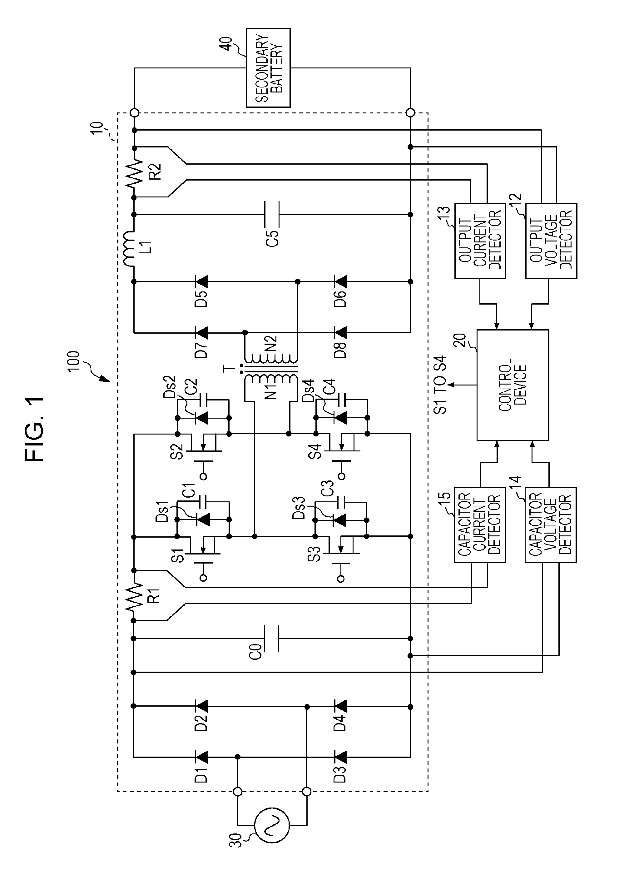
[0036]FIG. 1 illustrates a configuration example of an electric power converter 100 according to an embodiment. The electric power converter 100 is an AC-DC converter...
modified examples
[0085]The control device 20 may carry out feedback control on the basis of an output value from the output voltage detector 12 and / or the output current detector 13. This enables the output voltage and / or the output current to be controlled, and thereby constant voltage output and constant current output may be achieved. A duty method or a secondary-side phase shift method may, for example, be used as the output control method. The output control can be used concomitantly with the switching frequency control for suppressing ripples. The secondary-side phase shift method enables the switching frequency control and the output control to be carried out in the primary side and in the secondary side, respectively.
[Configuration of Electric Power Converter 100a]
[0086]FIG. 7 illustrates a configuration example of an electric power converter 100a according to a modified example. Hereinafter, part of the electric power converter 100a that differs from the electric power converter 100 illustr...
application example
[0106]The electric power converters described above can be used for various purposes. Hereinafter, an example in which an electric power converter described above is used as an in-vehicle charger will be described. The electric power converters according to the present embodiment may be used in quick chargers or contactless chargers installed outside vehicles, chargers for household batteries, AC-DC connection devices for energy monitoring systems, for example. The electric power converters according to the present embodiment may be used for charging secondary batteries with commercial power sources.
[0107]FIG. 8 is a block diagram illustrating a configuration example of a vehicle 200 in which the electric power converter 100 or 100a according to the present embodiment is provided. The vehicle 200, for example, is an electric vehicle or a plug-in hybrid vehicle. The vehicle 200 is provided with an outlet 201 for connecting to an external commercial power source, a charger constituted...
PUM
 Abstract
Description
Claims
Application Information