Image forming apparatus using technique for controlling power supply

a technology of power supply and image forming apparatus, which is applied in the direction of television system, coupling device connection, instruments, etc., can solve the problems of radiation noise, image quality deterioration, and output noise to be cut, so as to reduce power consumption and high-quality power supply

Active Publication Date: 2015-06-25
CANON KK
View PDF0 Cites 1 Cited by
  • Summary
  • Abstract
  • Description
  • Claims
  • Application Information

AI Technical Summary

Benefits of technology

[0010]The present invention provides an image forming apparatus that ensures high-quality power supply to an AFE and reduces power consumed by the AFE in sleep mode.

Problems solved by technology

A DC-DC converter is a power supply that has higher power conversion efficiency than that of the series path type regulator, but use of the DC-DC converter may cause ripple noise in output from the DC-DC converter due to the effect of switching.
For example, when power is supplied from the DC-DC converter to the reading unit, noise may affect an image in, for example, a mode where a low-intensity halftone image is read, causing image quality to deteriorate.
Thus, there is concern that the ripple noise could make radiation noise worse.
Further, in an image forming apparatus that carries out facsimile communications through an analog public line, undesired noise may propagate to the analog public line.
As a result, current flows from the circuit to which power is being supplied to the AFE to which no power is being supplied, and this causes a latch-up phenomenon or the like and may damage a device.
On the other hand, the series path regulator basically matches output voltage to desired output voltage by consuming power with a transistor or an FET and is thus inefficient in power conversion and not suitable for energy saving.

Method used


Image

  • Image forming apparatus using technique for controlling power supply
  • Image forming apparatus using technique for controlling power supply
  • Image forming apparatus using technique for controlling power supply

Examples


Embodiment Construction

[0025]The present invention will now be described with reference to the drawings showing an embodiment thereof.

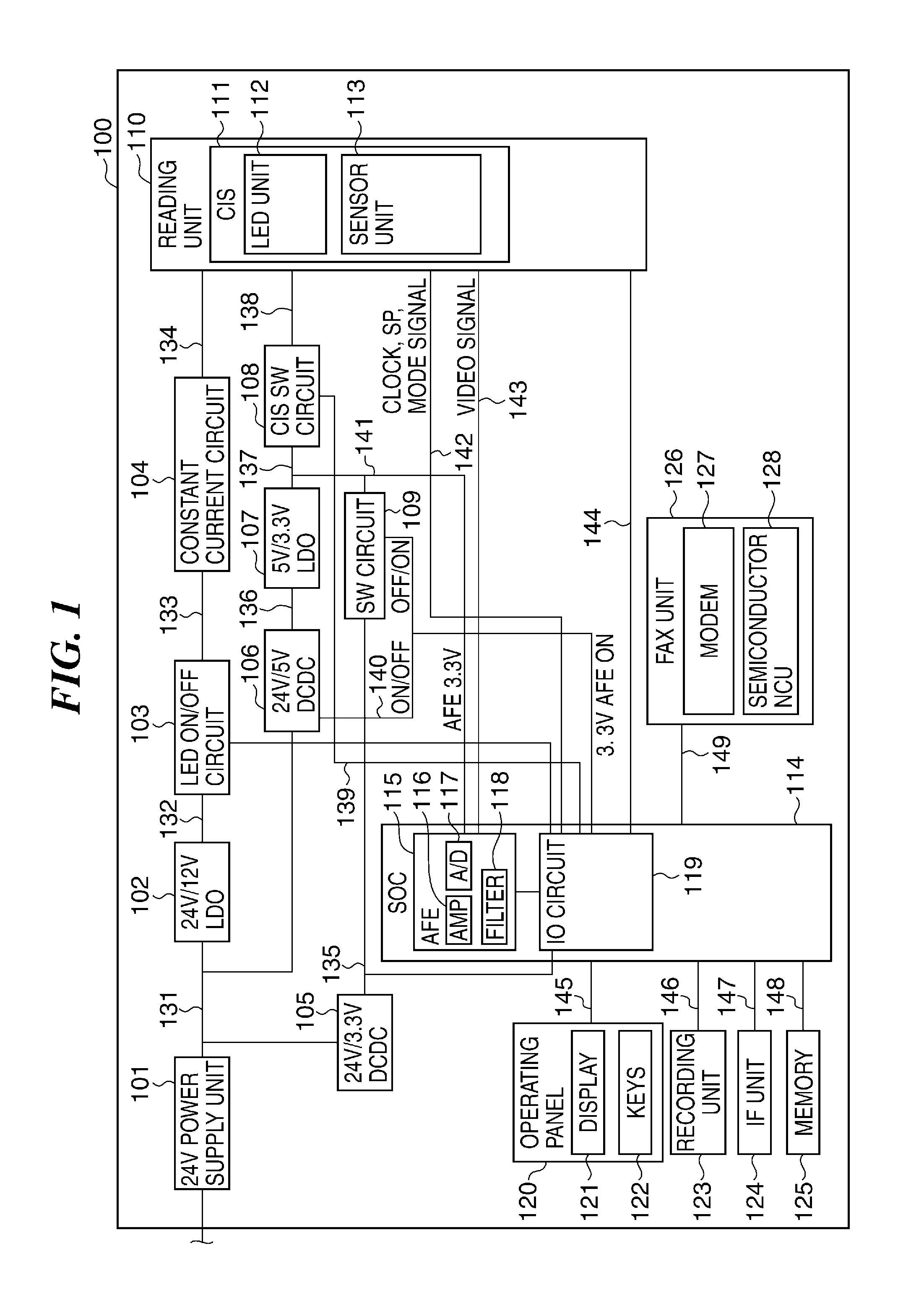
[0026]FIG. 1 is a block diagram schematically showing an arrangement of an image forming apparatus according to an embodiment of the present invention.

[0027]Referring to FIG. 1, the image forming apparatus 100 has components described hereafter.

[0028]A 24-V power supply unit 101 produces DC 24-V power from an AC commercial power supply (not shown) and supplies the DC power to an integrated circuit and others. A 24-V / 12-V_LDO 102 is a low drop-out regulator that converts DC 24-V power to DC 12-V power. An LED_ON / OFF circuit 103 turns on and off power supply to an LED unit 112. A constant current circuit 104 makes electric current for the LED 112 constant.

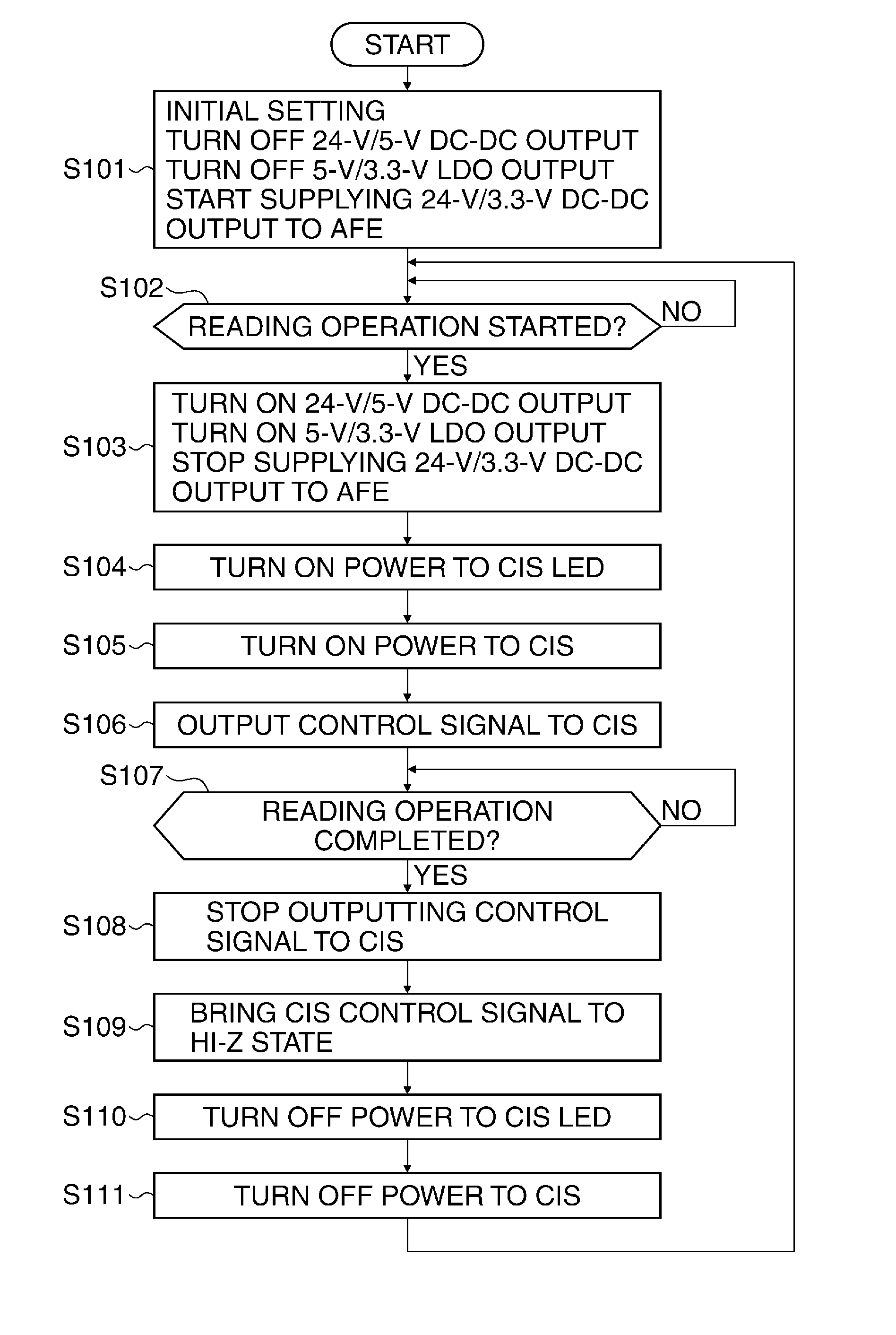
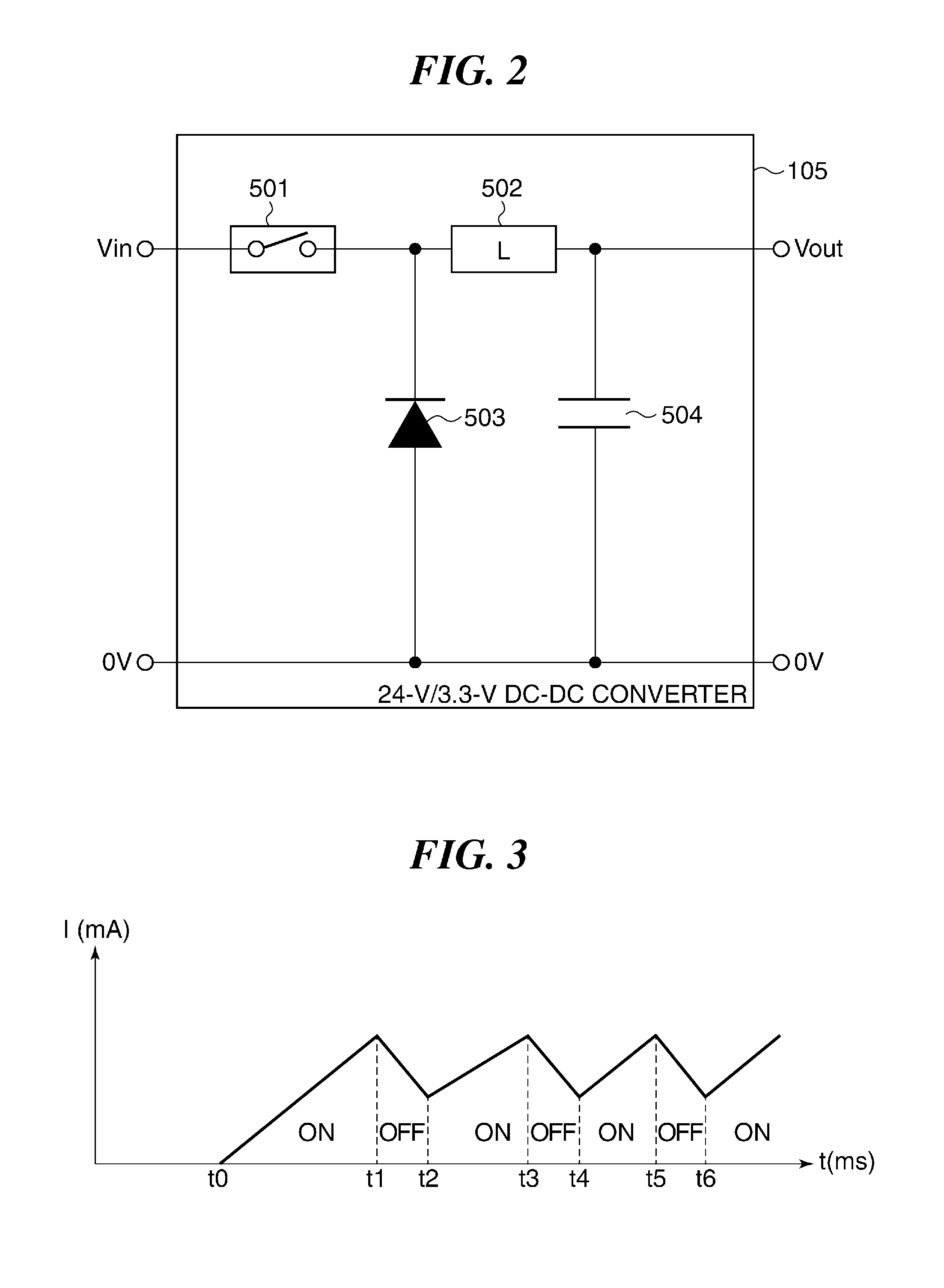
[0029]A 24-V / 3.3-V_DC-DC converter 105 is a DC-DC converter for producing DC 3.3-V power from DC 24-V power. A 24-V / 5-V_DC-DC converter 106 is a DC-DC converter for producing DC 5-V power from DC 24-V power.

[0030]A 5-V / 3.3-V...


PUM


Abstract

An image forming apparatus that ensures high-quality power supply to an AFE (analog front-end) and reduces the amount of power consumed by the AFE in sleep mode. The AFE, which converts an analog signal into a digital signal, and another circuit different from the AFE are incorporated in an SOC (system-on-a-chip). A switch circuit switches power to the AFE between first DC power supply from a 5-V/3.3-V_LDO and second DC power from a 24-V/3.3-V_DC-DC converter. When the AFE is in use, the switch circuit is controlled such that the first DC power is supplied from the 5-V/3.3-V_LDO to the AFE, and when the AFE is not in use, the switch circuit is controlled such that the second DC power is supplied from the 24-V/3.3-V_DC-DC converter to the AFE.

Description

BACKGROUND OF THE INVENTION[0001]1. Field of the Invention[0002]The present invention relates to an image forming apparatus, and in particular to a technique for controlling power supply to an integrated circuit constituting an image forming apparatus.[0003]2. Description of the Related Art[0004]In recent years, controller systems that use an integrated circuit called a system-on-a-chip (SOC) to control overall operation of an image forming apparatus have become widespread. As the SOC, one which incorporates an analog front-end (AFE) that converts an analog image signal into a digital signal is becoming common. The AFE has a filter circuit that removes noise from a read analog signal, an amplification circuit that amplifies an analog signal, and an A / D converter that converts an analog signal into a digital signal.[0005]Power to a reading unit, which is comprised of an AFE and a reading sensor such as a CIS or a CCD, is supplied from an accurate series path regulator (see, for examp...

Claims


Application Information

Patent Timeline
Patent Type & Authority Applications(United States)
IPC IPC(8): H04N1/00
CPCH04N1/00888H04N1/00901H04N1/00904G03G15/5004H02M1/4258H02M3/156H04N7/088G06F1/26G06F1/266H01R13/6675G06F1/263G06F1/3284G03G15/80H04N5/63H04N21/4436H02M1/0032Y02B70/10Y02D10/00
Inventor MIURA, SHIGEO
Owner CANON KK
Why Eureka
Try Eureka