Helical dynamic flow through heater

a heater and dynamic flow technology, applied in the direction of fluid heaters, lighting and heating apparatus, heat exchange apparatus, etc., can solve the problems of affecting the usability of the apparatus, challenging problems, and controlling such high heating power in order, and achieves simple and reliable forming, good total heat transfer, and good heat transfer

Active Publication Date: 2015-07-02
BLECKMANN
View PDF21 Cites 3 Cited by
  • Summary
  • Abstract
  • Description
  • Claims
  • Application Information

AI Technical Summary

Benefits of technology

[0026]In a preferred embodiment of the invention, the heat-conductive means may comprise a solder applied together with a soldering flux, wherein the method may further comprise soldering the fluid tube and the casing tube after the bending step by applying heat to the assembly of the casing tube and the fluid tube. This represents a very simple and reliable way of forming a soldering connection between the fluid tube and the casing tube simultaneously resulting in a very good total heat transfer from the heating coil to the fluid tube.
[0027]In another advantageous and independent embodiment, the method of the invention may comprise the step of applying a soldering flux onto the outer sur

Problems solved by technology

Controlling of such high heating power in order to produce a certain amount or a certain flow of water or steam having a specific temperature necessary to satisfy predetermined quality requirements is a challenging problem.
However, the high thermal inertia results in a long heating-up period when activating the beverage preparation apparatus so that usability of the apparatus is affected.
If, on the other hand, the heating device is operated in a stand-by mode so as to hold a predetermined higher temperature and shorten the heating-up period, then energy is wasted.
Furthermore, a lot of heat energy is provided to the thermal block during the heating-up period and lost useless when the apparatus is switched of and cools down.
However, manufacturing the heating device shown in DE 3542507 is laborious and expensive because first a complete tubular heating element has to be produced, and then the heating element and the water tube have to be slipped into the channels of the ex

Method used


Image

  • Helical dynamic flow through heater
  • Helical dynamic flow through heater
  • Helical dynamic flow through heater

Examples


first embodiment

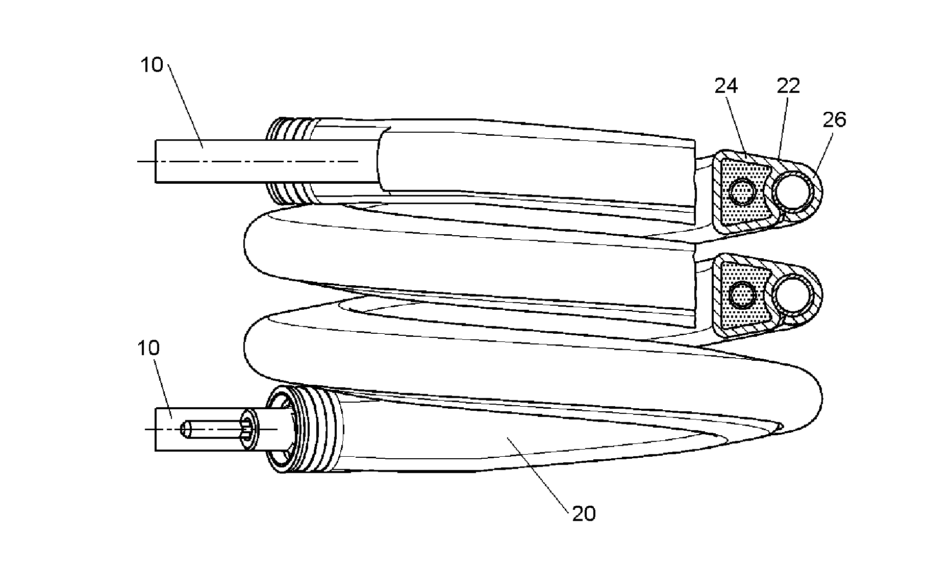
[0049]FIG. 1 is a perspective view of a helical assembly of a fluid tube 10 and a tubular heating element 20 of the flow through heater according to the invention. The tubular heating element 20, which is shown in FIG. 10 in more detail in a state before joining it with the fluid tube 10, is arranged adjacent to and in thermal contact with the fluid tube 10 in an approximately helical shape.

[0050]In alternative embodiments of the invention, the helical shape of the heater device may be a circular helix or an elliptical helix, or even a helix having an otherwise deformed cross section, as may be required by the space available for mounting the heater device in a beverage preparation apparatus, for example.

[0051]The fluid tube may be made of any material suitable to carry a fluid to be heated such as water or steam, and preferably is made of stainless steel which is a preferred material in the field of food technology because of its advantageous properties such as resistance to aggres...

second embodiment

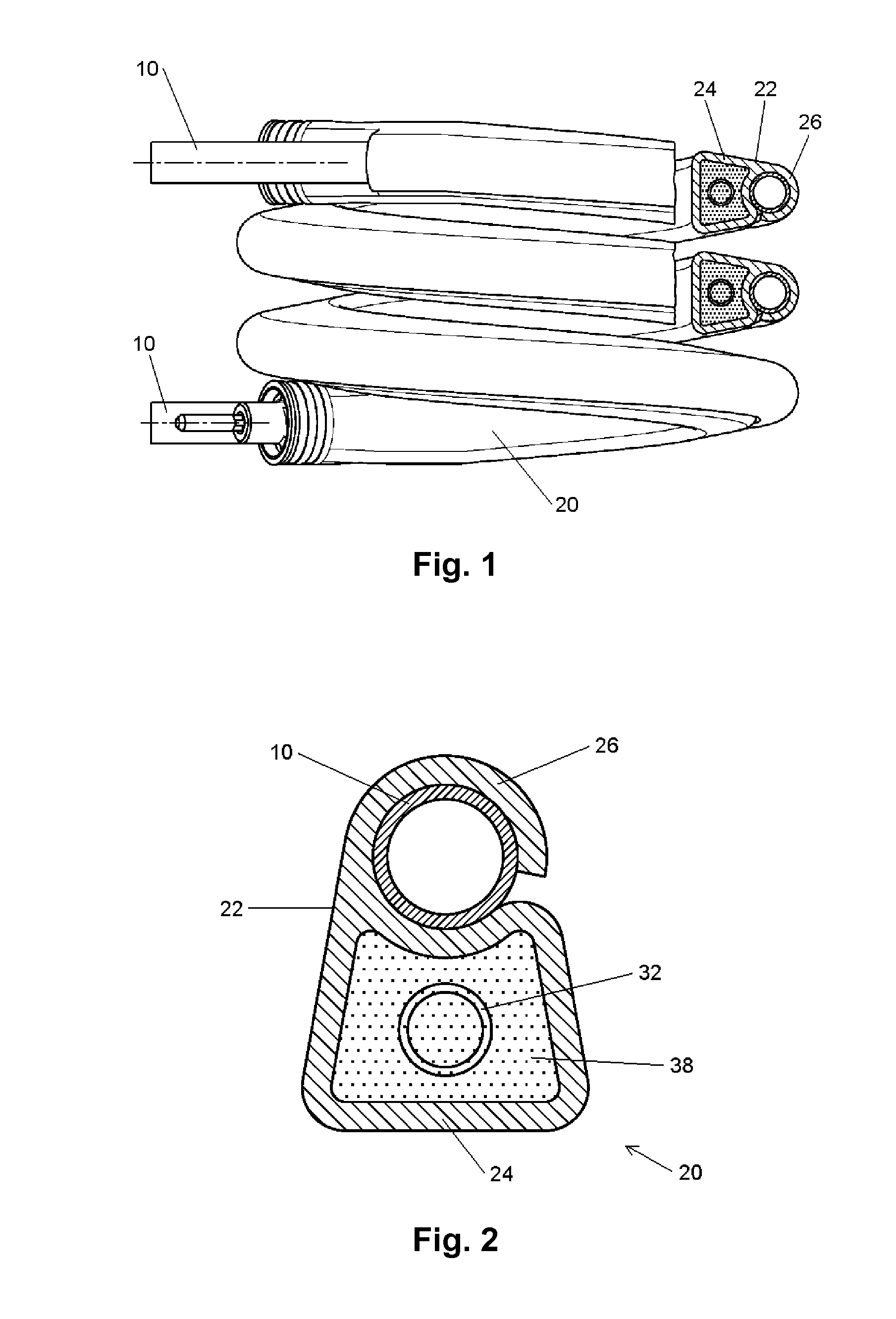
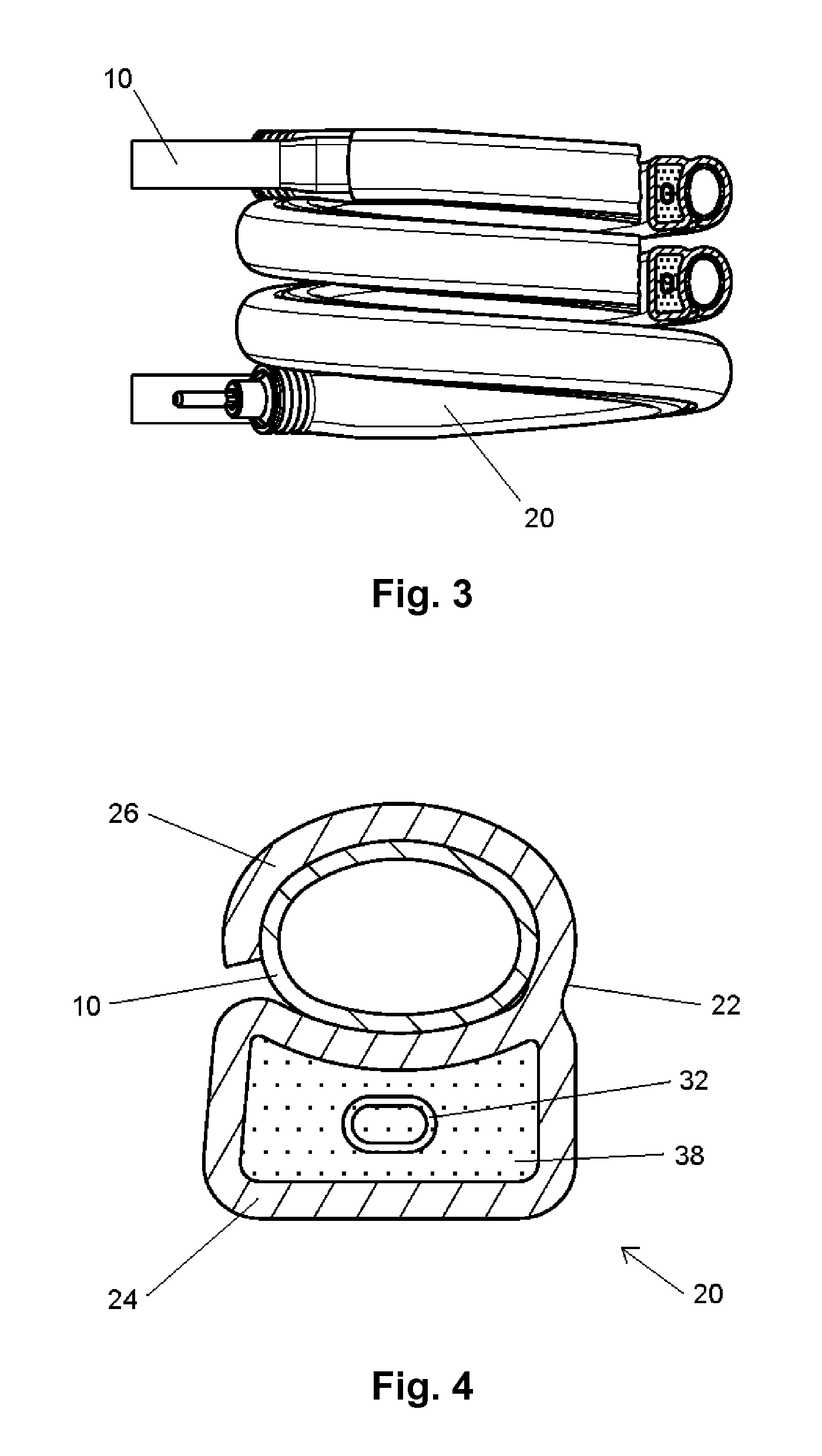
[0062]In the embodiment shown in FIGS. 1, 2, and the fluid tube 10 has a circular cross section. Alternatively, other cross sections of the fluid tube 10 are possible and may have additional advantages. For example, an elliptical cross section of the fluid tube 10 as shown in FIGS. 3, 4 and 12 may be used in a flow through heater according to the invention. An elliptical cross section results in a higher ratio of heated surface to flow cross section which may be preferred for certain applications.

[0063]An assembly of a second embodiment of the helical flow through heater device of the invention having an elliptical fluid tube is illustrated in FIGS. 3, 4 and 12. For this embodiment, a profiled casing tube 22 similar to that shown in FIG. 7 can be used.

[0064]A further independent and advantageous development of the invention is a third embodiment shown in FIGS. 5, 6 and 13 to 17. A profiled casing tube 122 of the third embodiment is shown in FIG. 13 and comprises two tab portions 126...

third embodiment

[0065]The profiled casing tube 122 of the third embodiment furthermore comprises a tubular portion 124 having a somewhat elongated cross section to receive a heating unit having two parallel heating coils 132a, 132b as shown in FIG. 6. Arranging two heating coils in the casing tube of the tubular heating element is a feature completely independent from the above mentioned feature of providing two tab portions, even though both features are illustrated in one embodiment shown in FIGS. 5, 6 and 13 to 17. In a further alternative option (not shown), the two heating coils 132a, 132b may be arranged coaxial to each other so that one heating coil is arranged within the other. Another alternative embodiment of the invention (not shown) may comprise a profiled casing tube having two adjacent tubular portions each receiving a separate heating coil, and two tab portions wrapped around a fluid tube. Providing two heating coils, which may have the same or a different electrical power, results i...


PUM

PropertyMeasurementUnit
Electrical conductoraaaaaaaaaa
Circumferenceaaaaaaaaaa
Heataaaaaaaaaa

Abstract

A flow though heater device comprising a fluid tube carrying a fluid to be heated, a tubular heating element extending at least partially parallel and in thermal contact with the fluid tube, wherein the tubular heating element comprises a profiled casing tube and at least one heating coil mounted in a tubular portion of said profiled casing tube. The profiled casing tube further comprises at least one tab portion laterally protruding from the tubular portion and being wrapped around the fluid tube, wherein the assembly of the fluid tube and the tubular heating element has an approximately helical shape so that the tubular portion of the casing tube is positioned with respect to the helix radially inside of the fluid tube.

Description

BACKGROUND[0001]1. Technical Field[0002]The present invention relates to flow through heater devices as used for example in coffee machines or other devices for preparing hot beverages and the like. In particular, the invention relates to a dynamic flow through heater having a helical shape, and a method of manufacturing such a helical flow though heater.[0003]2. Description of the Related Art[0004]In hot beverage preparation apparatuses like coffee machines, for example, electrical heating devices having an electrical power of several hundred watts up to more than 1 or 2 kW are used to produce hot water or steam for preparing a beverage. Controlling of such high heating power in order to produce a certain amount or a certain flow of water or steam having a specific temperature necessary to satisfy predetermined quality requirements is a challenging problem. One type of a common heating device comprises a kind of electrical heated massive thermo block having a relative heavy body ma...

Claims


Application Information

Patent Timeline
IPC IPC(8): A47J31/54B23P15/26
CPCB23P15/26A47J31/542F24H1/162H05B3/48Y10T29/49377
Inventor HOFER, JOHANNPLESCHINGER, ANDREAS
Owner BLECKMANN
Why Eureka
Try Eureka