Heat reclamation and air circulation device

a technology of air circulation device and heat reclamation, which is applied in the direction of ventilation system, heating type, lighting and heating apparatus, etc., can solve the problems of reducing overall heating requirements, reducing heat loss, and increasing heat loss, so as to reduce heat loss and improve power without significant increase in noise. , the effect of small siz

Inactive Publication Date: 2015-07-02
ZELMAN WILLIAM
View PDF0 Cites 10 Cited by
  • Summary
  • Abstract
  • Description
  • Claims
  • Application Information

AI Technical Summary

Benefits of technology

[0008]A suspended, lightweight, double walled fabric tube, heat reclamation and air circulation device of the present invention can be supported by an attachment device, such as a single small hook screwed into the ceiling of any room. It operates by pulling down warm air from beneath the ceiling and distributes it closer to the floor using a low-energy fan. Rotated 180 degrees in the vertical plane, the device will also bring cool air from the floor up to the ceiling, providing a cooling function. The outer wall of the double wall fabric tube provides insulation against heat or cooling loss and a pleasingly stable, translucent surface for incorporating lighting and artistic design embodiments. Within the outer tube wall and applied to the outer wall of the inner tube, are external springs holding open the inner fabric tube, which allow case of construction and maintenance of structural integrity of the inner fabric tube despite negative pressure generated by fan suction. In a single fan configuration, this spring arrangement allows the fan to be placed at the bottom of the structure where it is more efficient in moving air, and therefore can be sized smaller, and run slower and quieter. In a dual fan, push-pull configuration where one fan is at the top and one fan at the bottom of the tube, the device can provide improved power without significant increase in noise and without increasing the size of the fan or device. A deflector made of fabric allows for the most favorable directionality of airflow.
[0009]The spring device is of particular use in a pliable, tubular structure under negative air pressure. The spring can be added alter construction or placement of the tube is complete, using heavy duty tape, slipped into a formed pocket, or by a few sutures if slight air leakage is not of concern. The spring, or a combination of a plurality of springs, allows full function of the tube under negative pressure without the need for embedding internal reinforcing rings, coils, or stents within the lumen of the tube, which may therefore be constructed of inexpensive and lightweight fabrics, extrusions, films, and other similar lightweight relatively air impermeable materials.
[0010]The deflector may be a folded fabric or paper-like material. It is particularly desirable due to very low weight, low cost, simple construction, and ease of attachment using elastic bands, tape, glues, staples, clips or other bonding methods. The design is ideal for use in an air recirculation device that would be suspended from a ceiling and must be very lightweight.

Problems solved by technology

The greater the temperature differential between the ceiling and the air just beneath, the greater the rate of heat loss.
Bringing the heated air to the floor level thus lowers the rate of heat loss, and may lower heating requirements overall.
However these designs have significant constraints when applied to dwellings; either a device resting on the floor that must be fixed in place, a suspended system with a fan in the upper part of the duel close to the ceiling, requiring significant support, and relying on a circular motion of the lower tube to distribute air as well as an existing or installed ceiling electrical outlet.
These are constraints and expenses that many consumers might find objectionable.
Previous warming devices using a fan mounted at the ceiling, may be additionally compromised by lower efficiencies and greater noise generated by a fan pushing air downwards through a tube.

Method used


Image

  • Heat reclamation and air circulation device
  • Heat reclamation and air circulation device
  • Heat reclamation and air circulation device

Examples


Embodiment Construction

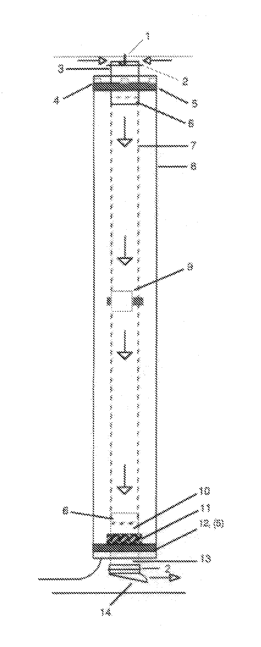
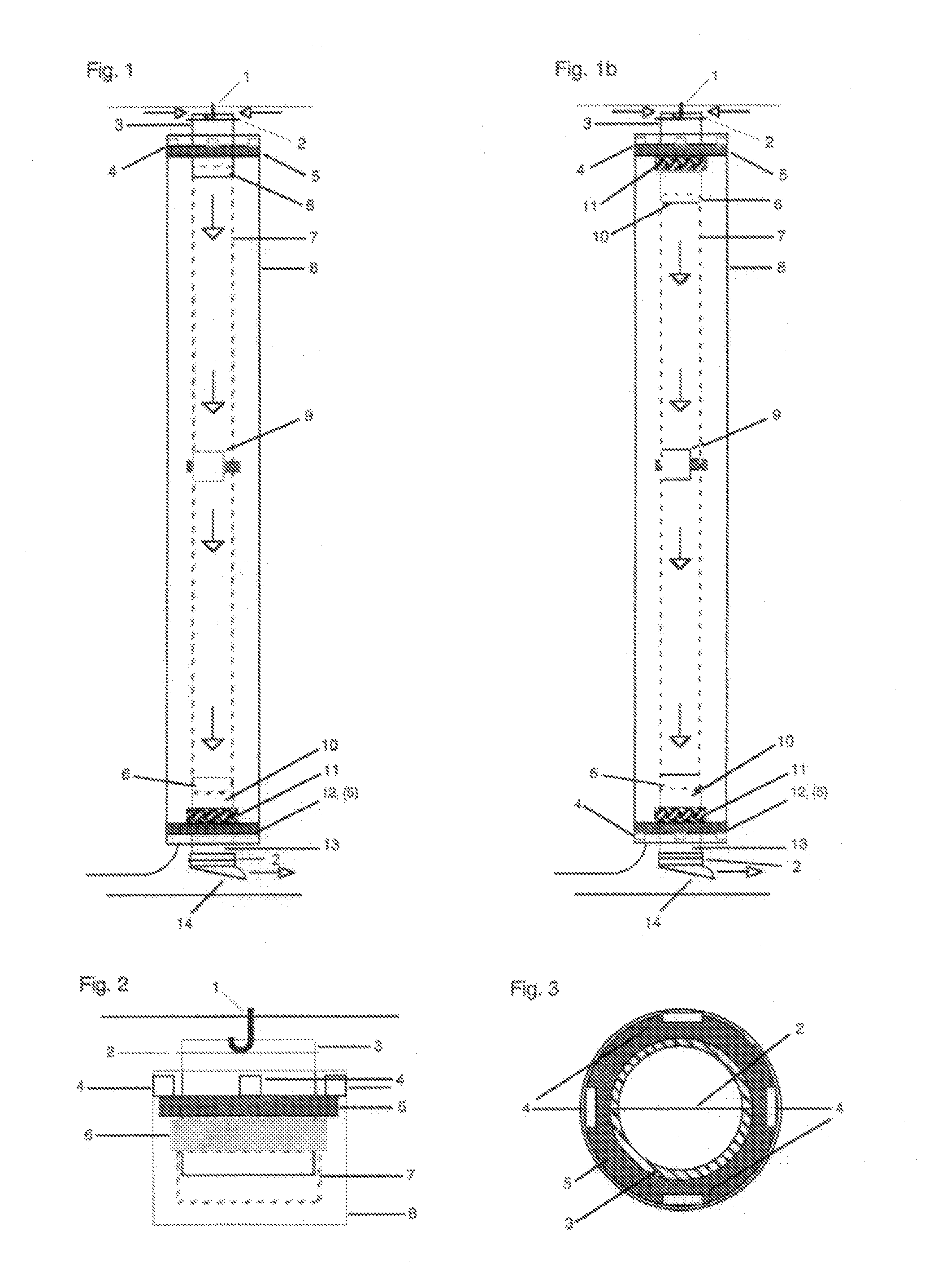
[0022]Referencing the accompanying drawings, in FIG. 1 a heat reclamation and recirculation device of the present invention is shown suspended by a small hook 1 screwed into the ceiling of a room. By using lightweight materials throughout the design, it is intended that the device will be suspended from any common ceiling material such as drywall, without requiring an anchor device beyond a small screw-in cup hook, and powered from below by a cord extending from the bottom of the device to a nearby wall outlet. For cooling, and powering the fan when the tube is rotated 180 degrees in the vertical plane, a parallel set of small power wires is affixed to the wall of the inner tube and ending in a power plug, in order to maintain a power connection at the bottom of the tube when placed in the new orientation. As the device has extremely modest electrical requirements, it is envisioned that a power source may ultimately be rechargeable batteries, or solar cells incorporated into the out...


PUM


Abstract

A device for reclaiming heated air near the ceiling of a room by circulating it to the lower portions of a room which reduces thermal stratification and distributes warm room air, which, improves comfort and heating efficiency, and in cooling mode, can be turned 180 degrees in the vertical plane to move cool air from the floor to the ceiling. Suspended from the ceiling by a small hook, the lightweight double walled fabric structure provides insulation against heat loss of the moving air, and contains a quiet and efficient fan at the bottom of the inner tube assembly which directs airflow into the room through a deflector crafted from a folded fabric sheet. The inner tube is held open against the negative pressure generated by suction of the fan by external springs attached to the outer wall of the inner tube, each spring fashioned from two struts connected by a short segment of elastic polymer.

Description

CROSS REFERENCE TO RELATED APPLICATIONS[0001]The present application is a non-provisional and claims the priority benefit of U.S. provisional application Ser. No. 61 / 922,386 filed Dec. 31,2013, and U.S. provisional application Ser. No. 61 / 940,844 tiled Feb. 18, 2014. The entire contents of both applications are incorporated herein by reference.BACKGROUND OF THE INVENTION[0002]1. Field of the Invention[0003]The present invention relates to systems for moving air in a building. More particular, the present invention relates to ducting systems to move air vertically but not limited thereto.[0004]2. Description of the Prior Art[0005]The invention is in the class of devices for generating air flow within a building structure or room, and having an upright air duct. Warm air rises to the cooler ceiling where the heat is conducted through to the next floor or roof. The greater the temperature differential between the ceiling and the air just beneath, the greater the rate of heat loss. Brin...

Claims


Application Information

Patent Timeline
Patent Type & Authority Applications(United States)
IPC IPC(8): F24F7/04F24F7/00
CPCF24F7/00F24F7/04F24F7/065
Inventor ZELMAN, WILLIAM
Owner ZELMAN WILLIAM
Why Eureka
Try Eureka