Methods of Multiple-Slice Coding for Frame Buffer Compression

a frame buffer and multiple-slice technology, applied in the field of image data processing, can solve the problems of limited throughput, increased transmission bandwidth and power consumption, and inability to display high-definition images

Active Publication Date: 2015-07-02
MEDIATEK INC
View PDF3 Cites 14 Cited by
  • Summary
  • Abstract
  • Description
  • Claims
  • Application Information

AI Technical Summary

Benefits of technology

[0014]Methods and apparatus are disclosed for encoding and decoding multiple slices of an image frame for frame buffer compression. According to the present invention, the encoding may be performed in an interleaving order on the multiple slices. The number of the encoder modules may be different from the number of the multiple slices in the image frame. One encoder module can be used to encode two or more slices in the image frame.

Problems solved by technology

When the display controller (DC) reads the pixels out from frame buffer at fixed rate, the requirement for the transmission bandwidth as well as the power consumption increases significantly to display high definition images.
Therefore, the throughput is limited because the multiple slices cannot be decoded in parallel by a multiple cores decoder without increasing frame buffer size.
However, for decoding each scan line based on vertical partition, only one de-compressor can be used since slice 1 processing cannot be started until slice 0 is finished.

Method used


Image

  • Methods of Multiple-Slice Coding for Frame Buffer Compression
  • Methods of Multiple-Slice Coding for Frame Buffer Compression
  • Methods of Multiple-Slice Coding for Frame Buffer Compression

Examples


first embodiment

[0050]According to the present invention, each slice is divided into multiple partitions. The encoding of the image frame is based on the partitions. Each partition may be less than, equal to or more than one row of compression blocks in each slice. Two or more slices can be compressed by one encoder module. The de-compression of multiple slices can also be performed by one decoder module.

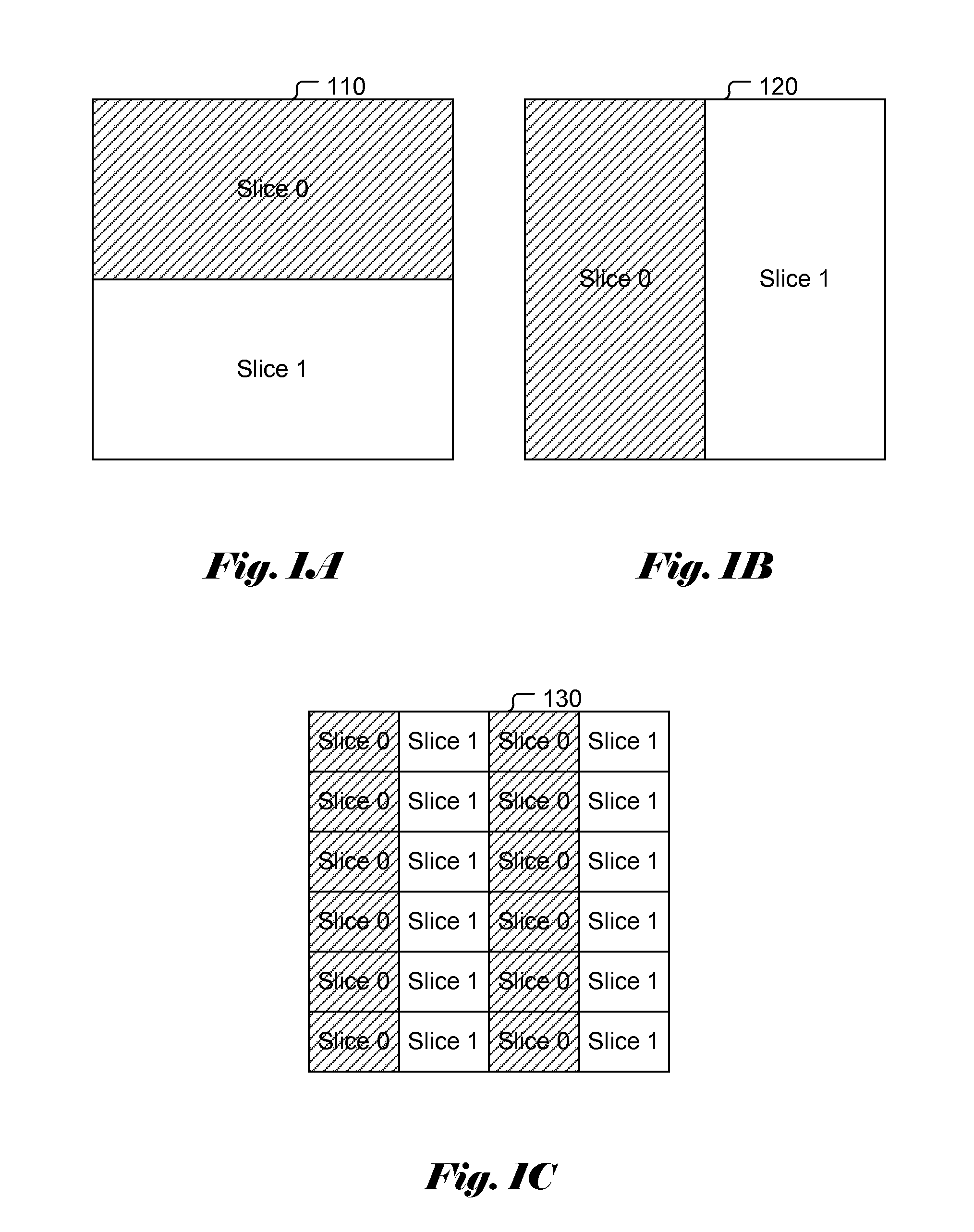
[0051]FIG. 5A illustrates an exemplary flowchart for encoder incorporating an embodiment of the present invention. After receiving an image frame in step 510, the image frame is divided into multiple slices in step 520. The multiple slices comprise slice 0 and slice 1. In this embodiment, each slice is further divided into multiple partitions for compressing in step 525. Each partition comprises one or more compression blocks. Each compression block is a rectangular pixel group consisting of one or more pixels.

[0052]In step 530, the encoder encoding each partition for each slice to generate a bitst...

second embodiment

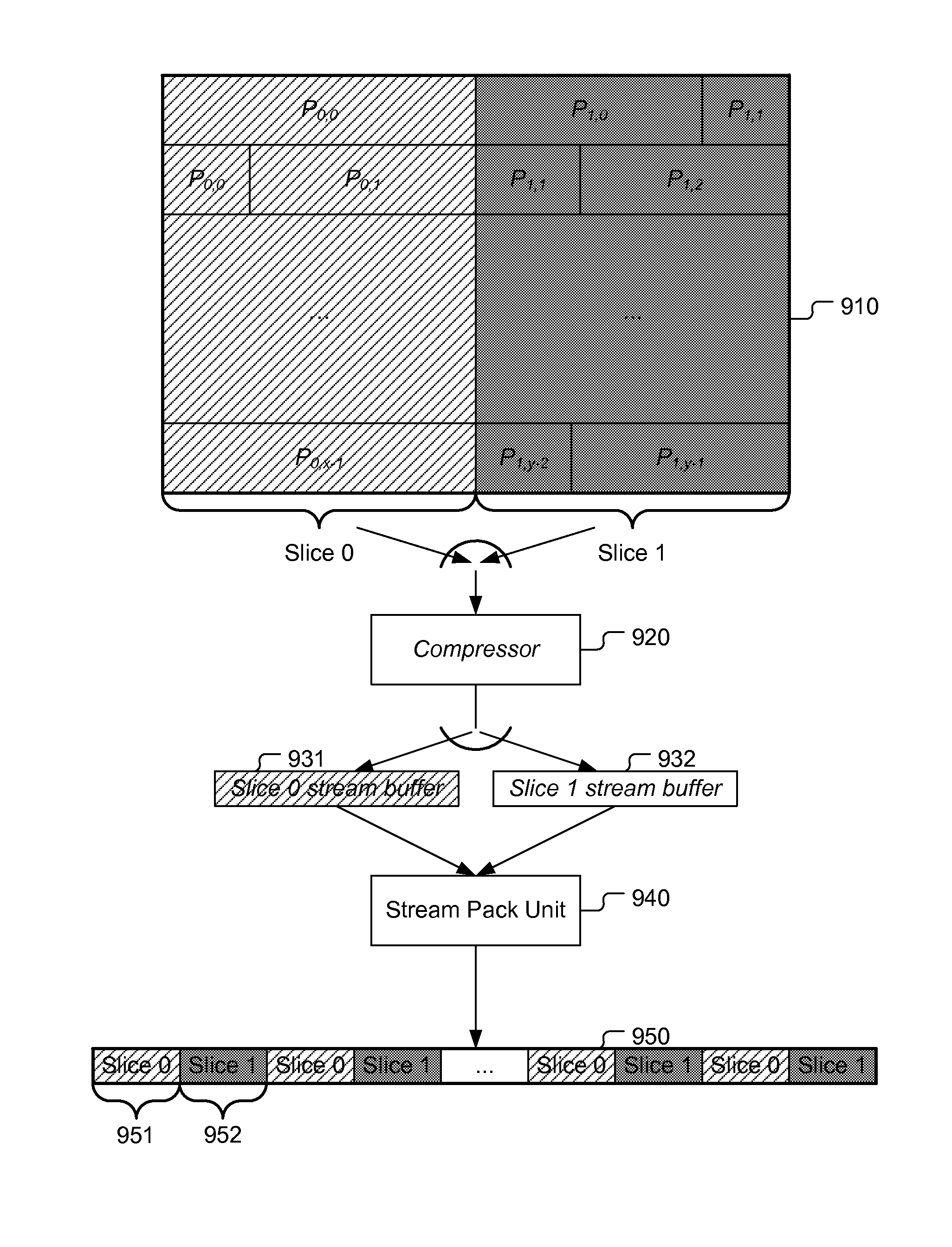
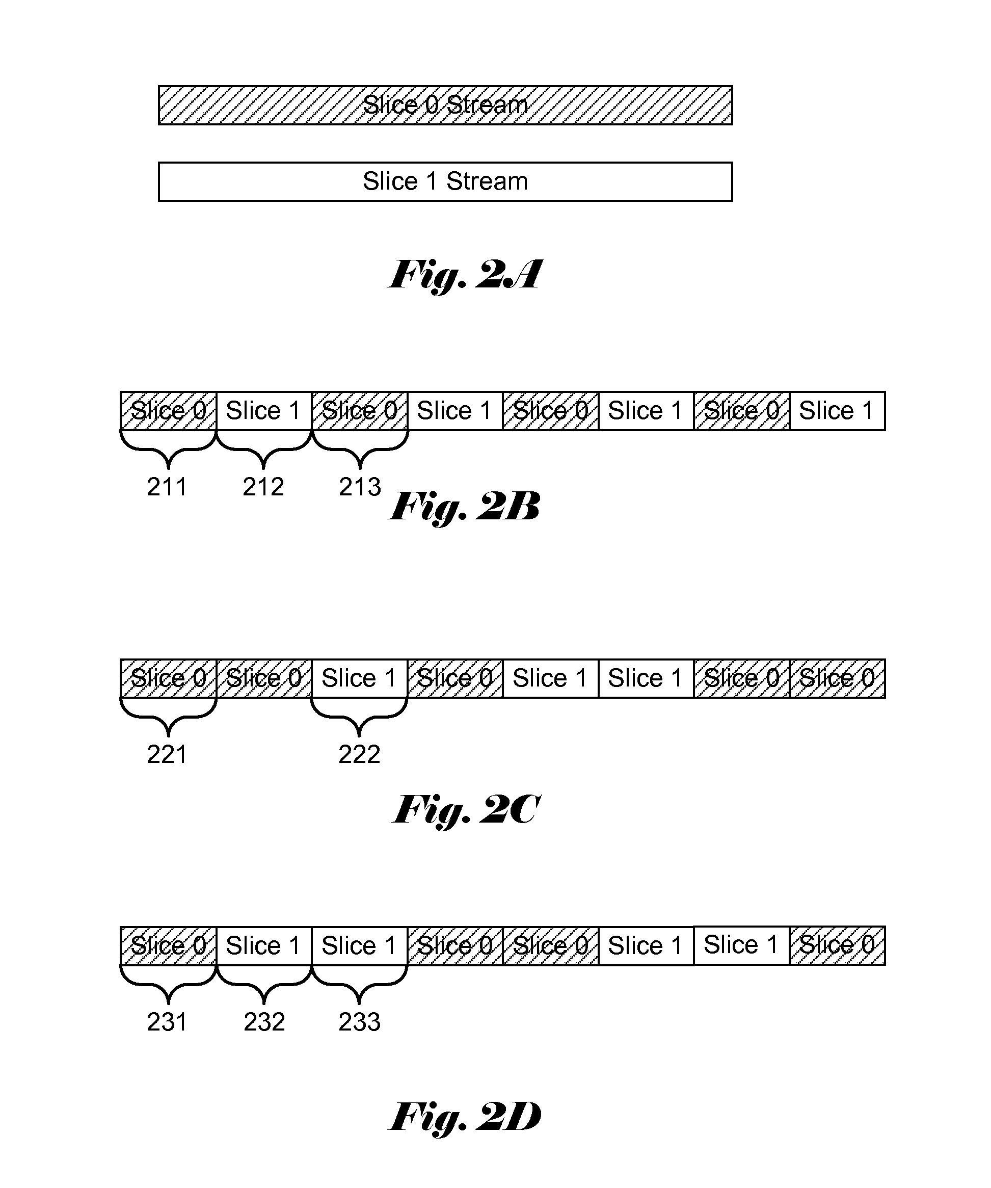
[0062]According to the present invention, the coding system encodes one part of one slice and switches to encode another slice based on the information related to the coding status associated with the multiple slices. The image frame is also divided into multiple slices which comprise slice 0 and slice 1. When one encoder module is used to encoding slice 0 and slice 1, the encoding of the slice 0 starts before the encoding of the slice 1. The information may be the pre-defined bitstream size, the amount of data stored in the corresponding stream buffer for the current slice, the fullness status of the corresponding stream buffer, the current encoding position in the image frame, the amount of data in the processing unit, or a combination of the foregoing.

[0063]If the amount of data in the processing unit may be used to determine the switch operation, the compressor may compress a pre-defined amount of data and switch to another slice. For example, the encoder is switch to another sl...


PUM


Abstract

Method is disclosed for reducing frame buffer, stream buffer, reconstruction buffer, or latency associated with frame buffer compression in an encoder or decoder with multiple slices of an image frame. The image frame is divided into multiple slices vertically, horizontally or both. One core compressor or decompressor can be used to process two or more slices. The encoding and decoding of two or more slices may be performed in parallel. Instead of encoding an entire slice, the encoder compresses only partial data of one slice before encoding another slice. According to one embodiment, each slice is divided into two or more partitions. The encoder is switched to another slice after encoding one partition of one slice. In another embodiment, the encoder is switched to another slice based the information related to the coding status. The decoding order may be same as the encoding order.

Description

CROSS REFERENCE TO RELATED APPLICATIONS[0001]The present invention claims priority to U.S. Provisional Patent Application, No. 61 / 920,841, filed on Dec. 26, 2013. This U.S. Provisional Patent Applications is hereby incorporated by reference in its entirety.FIELD OF THE INVENTION[0002]The present invention relates to image data processing. In particular, the present invention relates to methods of encoding and decoding an image frame with multiple slices for frame buffer compression.BACKGROUND[0003]With the development of image processing technique, the image display is improved from lower definition to higher definition. The amount of data to be transmitted increases significantly with the improvement of the definition, such as from 1280×720 to 1920×1088 or 2560×1600. When the display controller (DC) reads the pixels out from frame buffer at fixed rate, the requirement for the transmission bandwidth as well as the power consumption increases significantly to display high definition ...

Claims


Application Information

Patent Timeline
Patent Type & Authority Applications(United States)
IPC IPC(8): G06T1/60
CPCG06T1/60H04N19/119G06T2200/28H04N19/184H04N19/189H04N19/174H04N21/2343H04N21/4402H04N19/436
Inventor CHOU, HAN-LIANGLEE, KUN-BIN
Owner MEDIATEK INC
Why Eureka
Try Eureka