
Magnetic resonance imaging apparatus capable of acquiring selective gray matter image, and magnetic resonance image using same

a magnetic resonance imaging and selective gray matter technology, applied in the field of magnetic resonance imaging apparatus, can solve the problems of low signal to noise ratio (snr) for the acquired gray matter image, the difficulty of conventional double inversion recovery technique in acquiring high-resolution images, and the need for significant long time to acquire images. , to achieve the effect of short inversion time, long inversion time and reduced total imaging tim

Inactive Publication Date: 2015-07-09
KOREA UNIV RES & BUSINESS FOUND
View PDF10 Cites 7 Cited by
  • Summary
  • Abstract
  • Description
  • Claims
  • Application Information

AI Technical Summary

Benefits of technology

The patent text describes a magnetic resonance imaging technique that can significantly reduce the time it takes to get a high-resolution image of the gray matter in the brain. This is done by using only one inversion pulse to suppress the signal from the white matter. This technique also minimizes signal-to-noise ratio loss and allows for faster acquisition of the desired image. Overall, this technique has improved efficiency and image quality compared to conventional methods.

Problems solved by technology

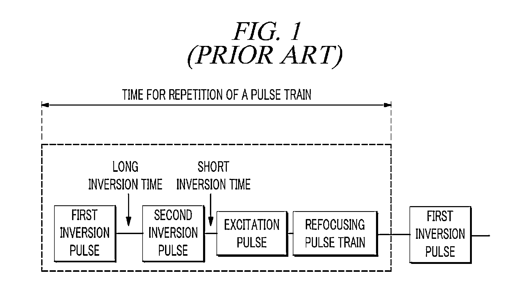
However, since the double inversion recovery technique uses the two (2) inversion pulses and the long and short inversion time, it has been problematic in that it requires significantly long time to acquire an image, and a signal to noise ratio (SNR) for the acquired gray matter image is low due to a reduction of the gray matter signal residual during the time of data acquisition for restoration of a final image.
Due to these problems, the conventional double inversion recovery technique has had difficulty in acquiring a high-resolution image, especially, the gray matter image at a high speed.

Method used


Image

  • Magnetic resonance imaging apparatus capable of acquiring selective gray matter image, and magnetic resonance image using same
  • Magnetic resonance imaging apparatus capable of acquiring selective gray matter image, and magnetic resonance image using same
  • Magnetic resonance imaging apparatus capable of acquiring selective gray matter image, and magnetic resonance image using same

Examples


Embodiment Construction

[0037]Hereinafter, example embodiments will be described in detail with reference to the accompanying drawings so that inventive concept may be readily implemented by those skilled in the art. However, it is to be noted that the present disclosure is not limited to the example embodiments, but can be realized in various other ways. In the drawings, certain parts not directly relevant to the description are omitted to enhance the clarity of the drawings, and like reference numerals denote like parts throughout the whole document.

[0038]Throughout the whole document, the terms “connected to” or “coupled to” are used to designate a connection or coupling of one element to another element and include both a case where an element is “directly connected or coupled to” another element and a case where an element is “electronically connected or coupled to” another element via still another element. Further, the term “comprises or includes” and / or “comprising or including” means that one or m...


PUM


Abstract

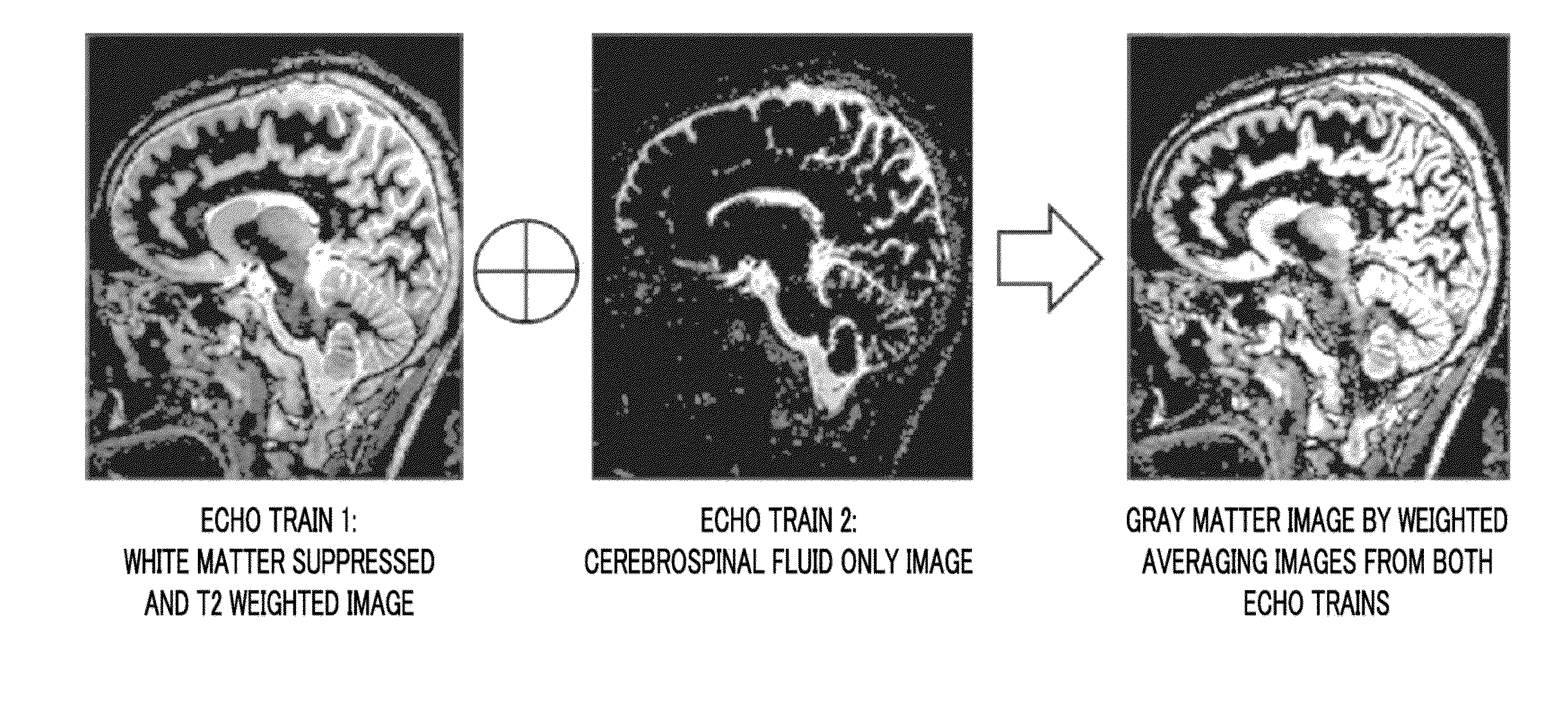
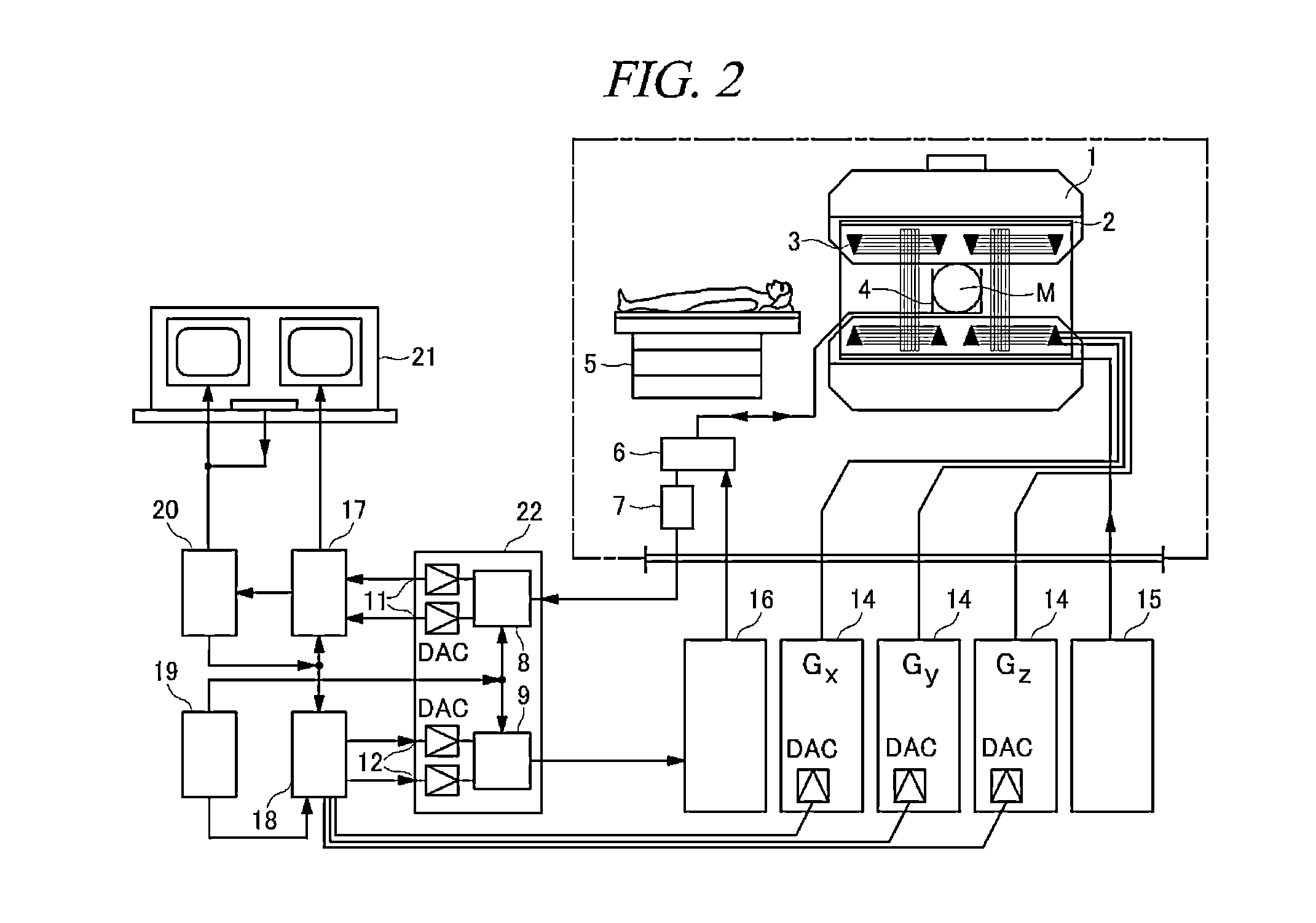
There is provided a magnetic resonance imaging apparatus comprising: an inversion pulse generating unit that applies an inversion pulse to a living body to suppress a white matter image signal; an excitation pulse generating unit that applies an RF excitation pulse to the living body after inversion time from the inversion pulse so as to excite magnetization; an image signal receiving unit that acquires first and second final image signals from first and second echo trains in an RF refocusing pulse train, respectively; and an image generating unit that generates a gray matter image from the first and second final image signals.

Description

TECHNICAL FIELD[0001]The embodiments described herein pertain generally to a magnetic resonance imaging apparatus and a method for acquiring a magnetic resonance image by using the magnetic resonance imaging apparatus, in particular, a magnetic resonance imaging apparatus, which is capable of acquiring a selective gray matter image, and a method for acquiring a magnetic resonance image.BACKGROUND[0002]In recent, there have been increasing cases of acquiring an image of a human body in a lateral direction, a longitudinal direction, a diagonal direction and other directions by using a magnetic resonance imaging (MRI) apparatus, and examining and diagnosing the state of a person to be examined through the image.[0003]A technique of acquiring an image having high resolution and contrast is being researched for more exact diagnosis, and especially, a technique of selectively displaying an image related to interested information within a final image acquired in the magnetic resonance imag...

Claims


Application Information

Patent Timeline
IPC IPC(8): A61B5/00A61B5/055G06T11/00
CPCA61B5/0042G06T11/008A61B5/055A61B2576/026G06T2207/20216G06T2207/30016G06T2207/10088G01R33/5602G01R33/5617G16H30/40
Inventor PARK, JAESEOKLEE, HYUNYEOL
Owner KOREA UNIV RES & BUSINESS FOUND
Learn More