
Spherical bearing and plastic block with spherical surface for the same

a technology of spherical surface and plastic block, which is applied in the direction of bridges, mechanical devices, bridge structural details, etc., can solve the problems of high price of traditional spherical bearings (b>10/b>) using brass spherical blocks (b>20/b>), and achieve excellent vertical resistance, easy production, and reduced size

Active Publication Date: 2015-07-09
R J WATSON +1
View PDF8 Cites 18 Cited by
  • Summary
  • Abstract
  • Description
  • Claims
  • Application Information

AI Technical Summary

Benefits of technology

The spherical bearing described in this patent offers a lighter and smaller design compared to conventional bearings. It eliminates the need for a separate slider and groove, making it easier to manufacture. The engineering plastic used for the spherical block also makes the bearing more durable and resistant to rust. The low coefficient of static friction and excellent anti-abrasion properties of the spherical block also contribute to its long life and stability. Overall, the technical effects of this patent are improved performance, durability, and reduced size of the spherical bearing.

Problems solved by technology

The brass has an excellent anti-abrasiveness, but since it is much more expensive than regular bearing material the traditional spherical bearing (10) using the brass spherical block (20) is very expensive.

Method used


Image

  • Spherical bearing and plastic block with spherical surface for the same
  • Spherical bearing and plastic block with spherical surface for the same
  • Spherical bearing and plastic block with spherical surface for the same

Examples


Embodiment Construction

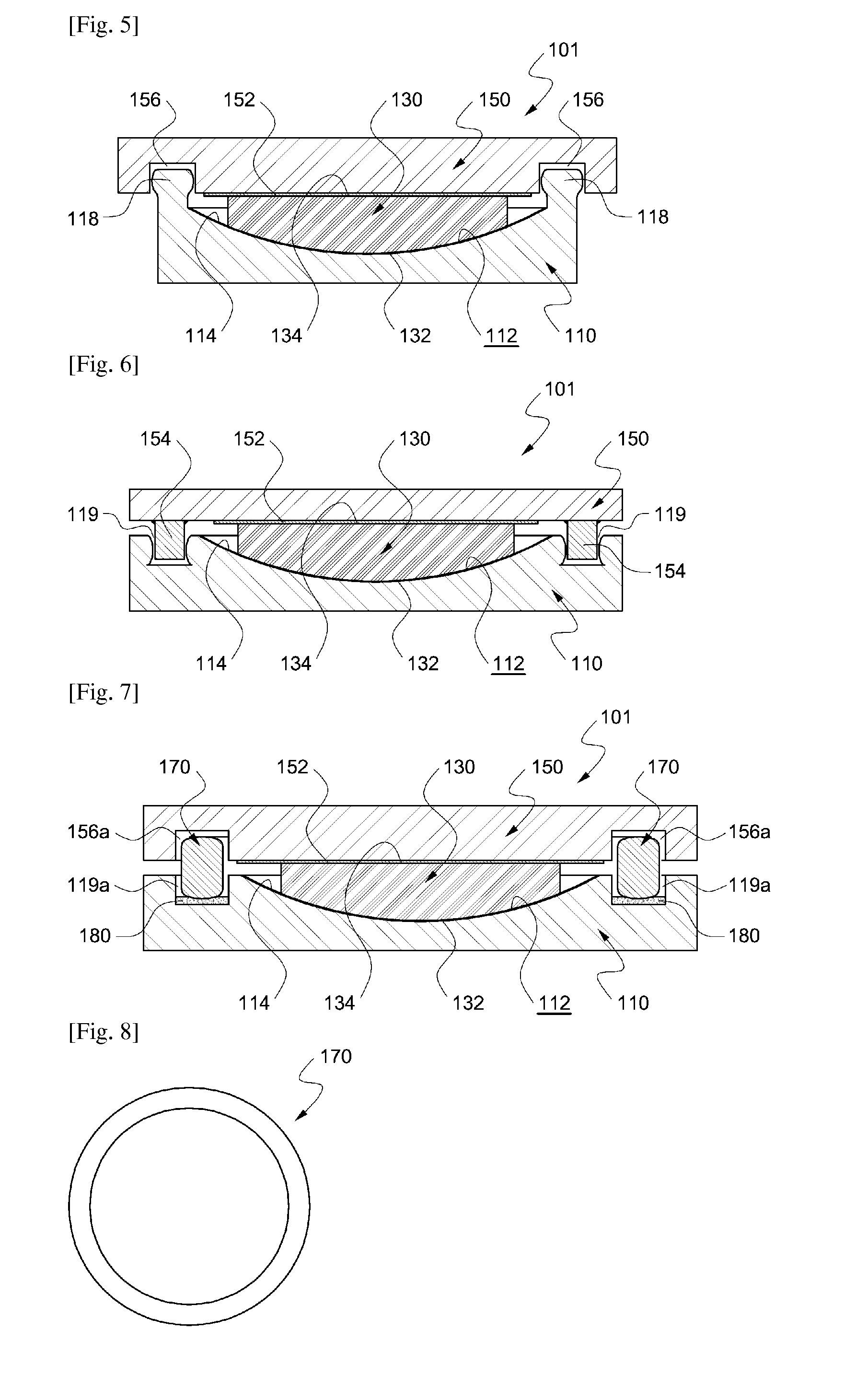
[0067]Below, referring to the attached drawings, preferable embodiments of the invention are going to be described in detail.

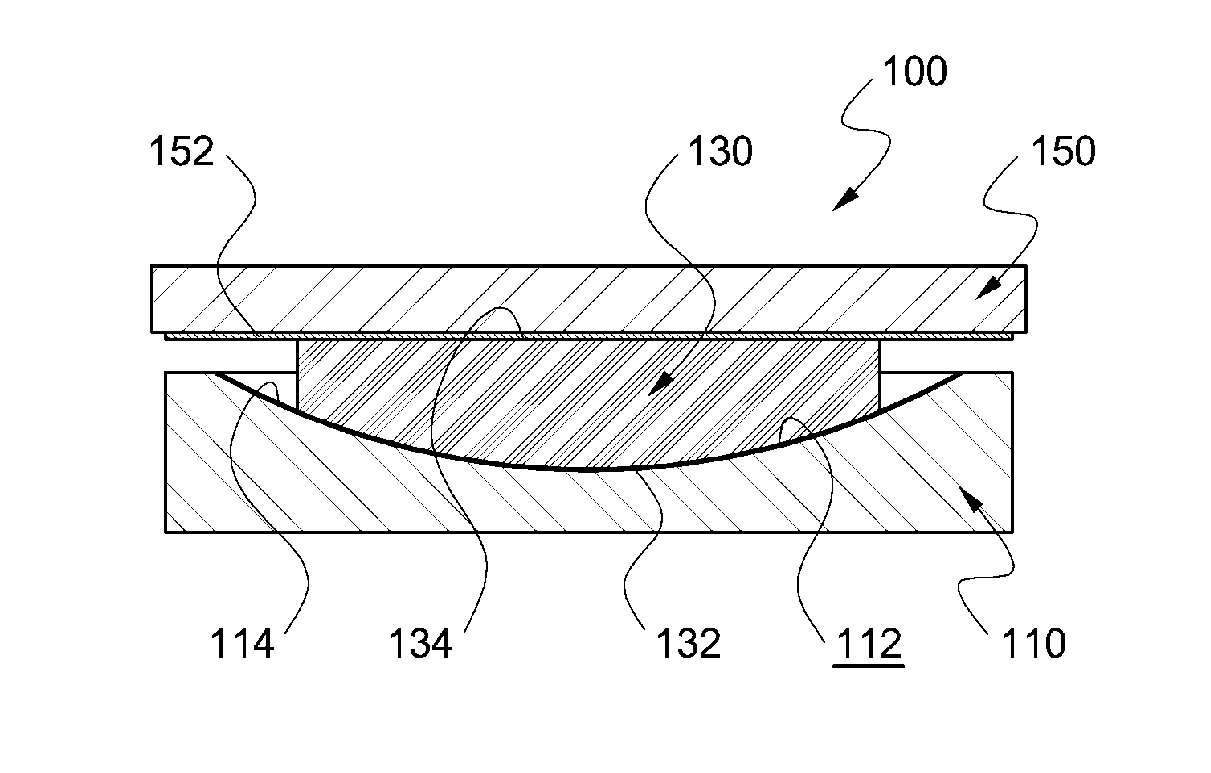
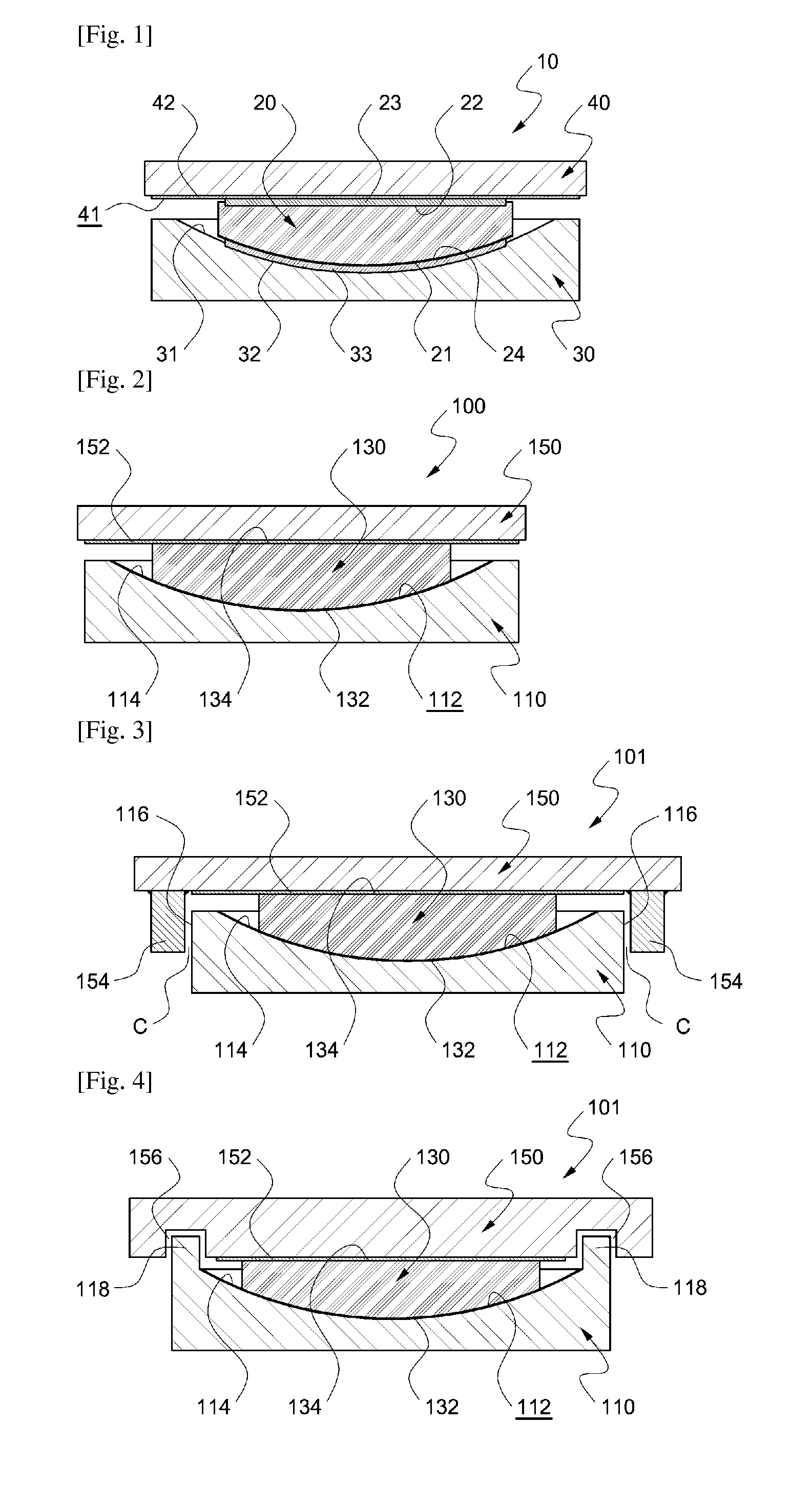
[0068]FIG. 2 is a cross-sectional view showing an example of a spherical bearing for operating in both directions according to the invention.

[0069]Referring to FIG. 2, the spherical bearing (100) according to the invention comprises a spherical groove member (110). On a top surface of the spherical groove member (110) is formed a spherical groove (112). This spherical groove (112) is a part which a convex spherical surface (132) of a plastic spherical block (130) described later engages and surface-contacts, and its curvature is preferably same as that of the convex spherical surface (132). On a surface of such spherical groove (112) is formed a chrome-plating layer (114). The chrome-plating layer (114) is for reducing friction against the plastic spherical block (130).

[0070]This spherical bearing (100) is allowed to rotate upward and downward with respect to ...


PUM


Abstract

A spherical bearing is disclosed, which is easy to make, can be made small, and does not have a sticking problem of a spherical block. The spherical bearing includes a plastic spherical block made of plastic and including a convex spherical surface, a spherical groove member including a spherical groove with which the convex spherical surface engages and surface-contacts and allowing rotation with respect to the plastic spherical block, and a weight-delivering member installed opposite to the spherical groove member with the plastic spherical block in the middle, and wherein a frictional surface of the plastic spherical block rubbing against the spherical groove member or the weight-delivering member is made of engineering plastic such as PA, POM etc. having a hardness of 75D through 95D.

Description

TECHNICAL FIELD[0001]The present invention relates to a spherical bearing used to support a massive structure such as an upper structure of a bridge and a spherical block for the same.BACKGROUND ART[0002]In general, a spherical bearing is installed between an upper structure of a bridge and a pier and delivers the weight from the upper structure to the pier, and also is installed widely in bridges which need functions of allowing the thermal expansion or contractions of the upper structure, supporting the dynamic weight when a car or a train starts or brakes, absorbing shock when an earthquake breaks out, and preventing the dislocation of the upper structure by a negative reaction, for example, a railroad bridge. Such a spherical bearing is going to be explained referring to FIG. 1.[0003]FIG. 1 is a cross-sectional view showing an exemplary spherical bearing in a prior art.[0004]The spherical bearing (10) shown in FIG. 1 is a supporting device, which is installed between an upper st...

Claims


Application Information

Patent Timeline
IPC IPC(8): E01D19/04
CPCE01D19/046F16C13/04F16C13/06F16C2350/00E01D19/04F16F15/02
Inventor KIM, SUNG KYU
Owner R J WATSON
Learn More