
Random Number Generator Using Ring Oscillators With Initial Delay

a technology of ring oscillator and initial delay, applied in pulse generators, pulse techniques, instruments, etc., can solve the problems of unintentional creation of random circuit variations in prior art designs, unpredictability of transitioning,

Active Publication Date: 2015-07-09
THE UNITED STATES OF AMERICA AS REPRESETNED BY THE SEC OF THE AIR FORCE
View PDF7 Cites 5 Cited by
  • Summary
  • Abstract
  • Description
  • Claims
  • Application Information

AI Technical Summary

Benefits of technology

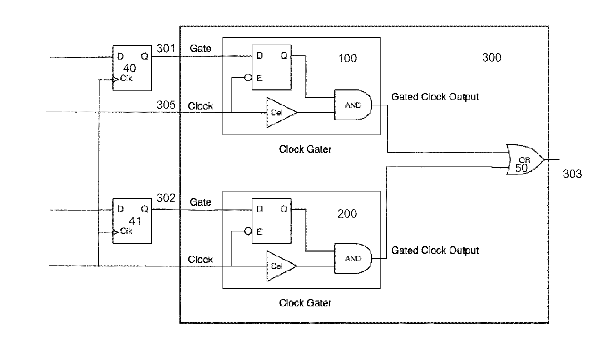
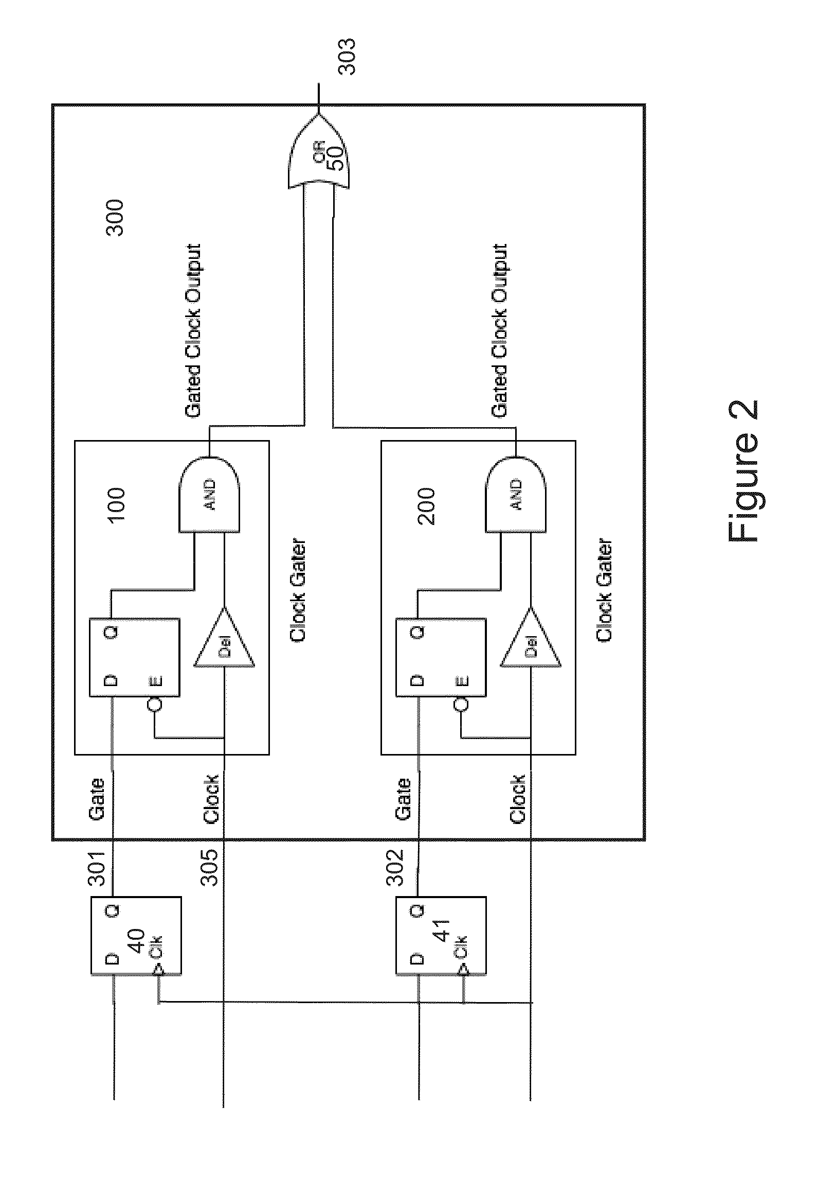
The present invention provides an apparatus and method that improves the generation of random bits by intentionally staggering the startup of ring oscillators across their oscillation cycles using a delay circuit. This helps ensure that the bits generated are truly random.

Problems solved by technology

The results of those that are transitioning will not be predictable due to noise.
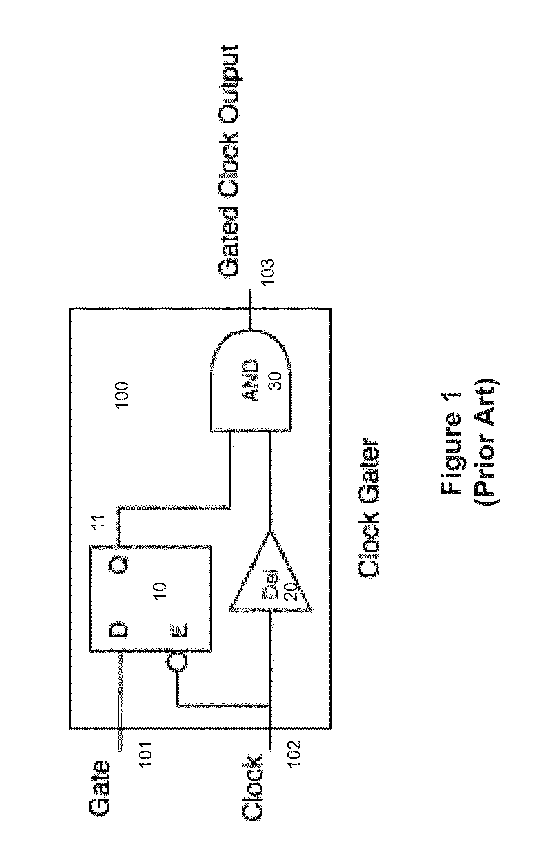
Prior art designs have relied on random circuit variations unintentionally created during manufacturing to ensure the ring oscillators have slightly different phases between each of the many ring oscillators in the design.

Method used


Image

  • Random Number Generator Using Ring Oscillators With Initial Delay
  • Random Number Generator Using Ring Oscillators With Initial Delay
  • Random Number Generator Using Ring Oscillators With Initial Delay

Examples


Embodiment Construction

[0009]Referring to FIG. 1, the key components of a prior art ring oscillator random number generator are shown. An odd number of inverters 10, 11, 12, 13, 14 shown in the top most ring oscillator, 1 are connected in a loop that includes an AND gate 20, used to enable the ring oscillator. When AND gate 20 has a “1” on input 21 the looped back ring consisting of 10 driving 11, 11 driving 12, 12 driving 13, 13 driving 14, 14 driving AND gate input 22 will oscillate. The oscillation period is twice the propagation delay time through the looped circuitry since two passes through the loop are required to return to the original value.

[0010]Still referring to FIG. 1, the output of each ring is captured by flip-flops 30, 31, through 37, which are clocked at a much slower frequency than the ring oscillator's frequency. The outputs of flip-flops 30, 31 through 37, are processed through XOR gates 40 through 46. The output 47 will be random if any one or more of the flip-flops 30, 31 through 37,...


PUM


Abstract

Apparatus and method for a ring oscillator based random number generator with intentional startup delays timed for each ring to provide a uniform initial spreading of the ring oscillator transition edges. This invention adds a controlled incremental delay in the startup of each individual ring within the ring oscillator random number generator. Typically the delay units used in the ring oscillators themselves can be used to get a course delay between the start times of each ring. A subset of the rings start up with a particular course delay and different fine delays such that the transition edges of all the rings are spread out over the oscillation period. This spreading of the transition edges ensures the output of the random number generator are not a predictable sequence of ones and zeros based on a simultaneous startup of all rings at the same time.

Description

PRIORITY CLAIM UNDER 35 U.S.C. §119(e)[0001]This patent application claims the priority benefit of the filing date of provisional application Ser. No. 61 / 817,368, having been filed in the United States Patent and Trademark Office on Apr. 30, 2013 and now incorporated by reference herein.STATEMENT OF GOVERNMENT INTEREST[0002]The invention described herein may be manufactured and used by or for the Government for governmental purposes without the payment of any royalty thereon.BACKGROUND OF THE INVENTION[0003]One method of generating a random number on a digital integrated circuit is to use a number of ring oscillators, (typically an odd number of digital inverters connected in a loop), with their outputs latched and those latched values having an XOR function performed on them. If the individual ring oscillators have different phases the output cannot be predicted because the capture of the current output state (0 or 1) by the latches will include capturing of some transitioning edge...

Claims


Application Information

Patent Timeline
Patent Type & Authority Applications(United States)
IPC IPC(8): G06F7/58H03K3/03H03K3/84
CPCG06F7/588G06F2207/58H03K3/0315H03K3/84
Inventor ROOKS, JOHN W.
Owner THE UNITED STATES OF AMERICA AS REPRESETNED BY THE SEC OF THE AIR FORCE
Learn More