Endblock for rotatable target with electrical connection between collector and rotor at pressure less than atmospheric pressure

a technology of endblocks and rotatable targets, applied in the field of end, can solve the problems of constant change of tube shape, difficult to take into account the task, and the dependence and serviceability of magnetrons, and achieve the effect of improving the sputtering ra

Active Publication Date: 2015-07-16
GUARDIAN GLASS LLC +1
View PDF3 Cites 5 Cited by
  • Summary
  • Abstract
  • Description
  • Claims
  • Application Information

AI Technical Summary

Benefits of technology

[0007]It has surprisingly been found that a new design that includes locating the electrical contact(s) (e.g., brushes) between the collector and rotor in an area under vacuum (as opposed to in an area at atmospheric pressure as in conventional FIG. 1) provides for significant advantages over the conventional design. Moving the power connection between the rotor and collector to an area under vacuum (an area at a pressure less than atmospheric pressure), for example, allows for a structure where both the rotor and collector can be efficiently cooled (e.g., water cooled) which has surprisingly been found to allow the sputtering rate to be improved (e.g., up to a 20% improvement in sputtering rate has surprisingly been found compared to the conventional FIG. 1 design). A rotating sputtering target, such as a magnetron sputtering target, is often supported by two endblocks—one at each end of the target. One or both of the endblocks for supporting a rotating target may be designed in accordance with example embodiments of this invention.

Problems solved by technology

In addition to the quality of the coating the magnetron deposits upon the substrate, dependability and serviceability of the magnetron is an issue.
This is not an easy task taking into account the constraints of the process that is involved.
Another complication is that the sputtering actually erodes the target tube during the sputtering process, so the target tube is constantly changing shape during its serviceable lifetime.

Method used


Image

  • Endblock for rotatable target with electrical connection between collector and rotor at pressure less than atmospheric pressure
  • Endblock for rotatable target with electrical connection between collector and rotor at pressure less than atmospheric pressure
  • Endblock for rotatable target with electrical connection between collector and rotor at pressure less than atmospheric pressure

Examples


Embodiment Construction

[0013]Referring now more particularly to the accompanying drawings in which like reference numerals indicate like parts throughout the figures.

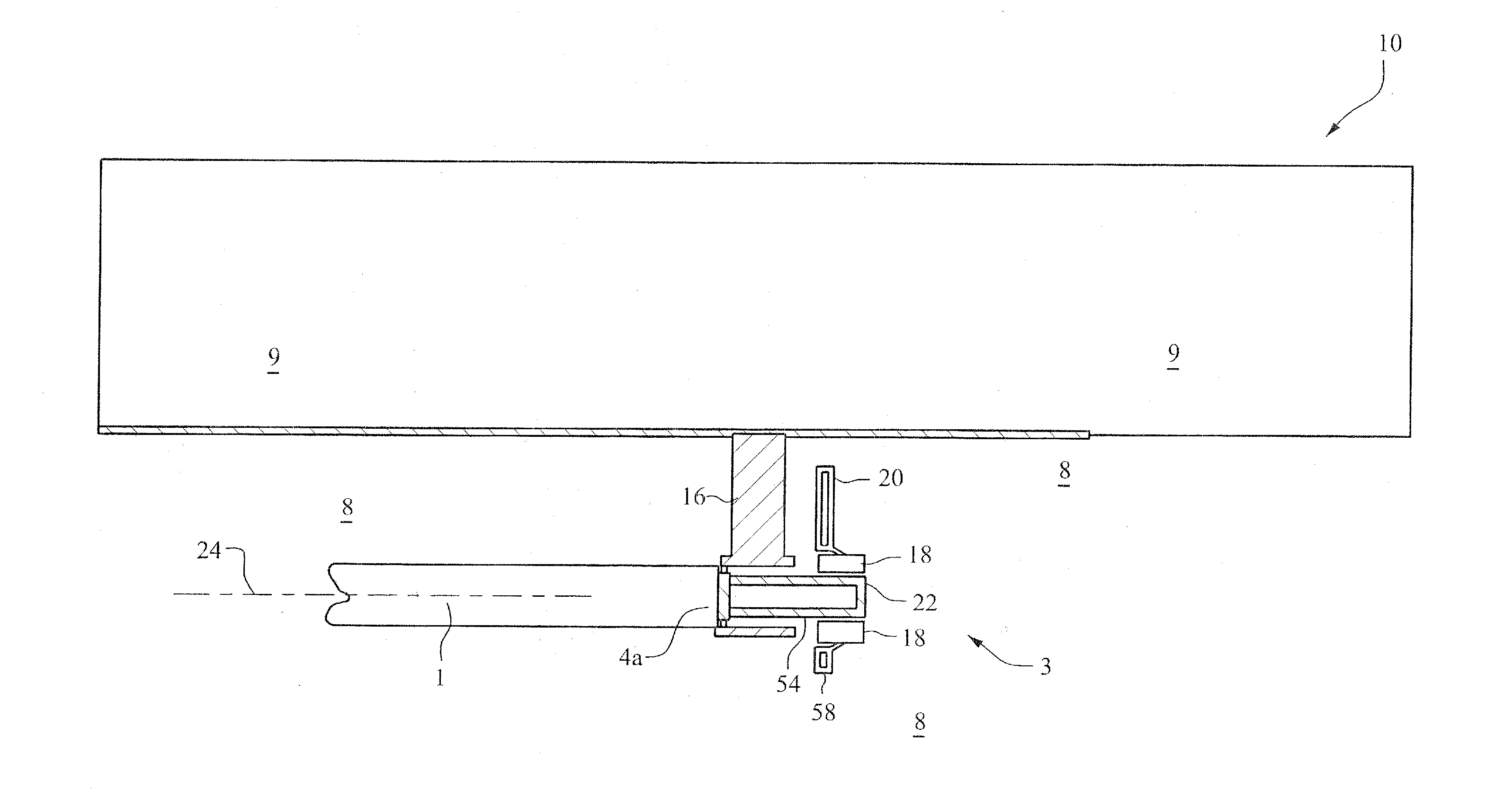
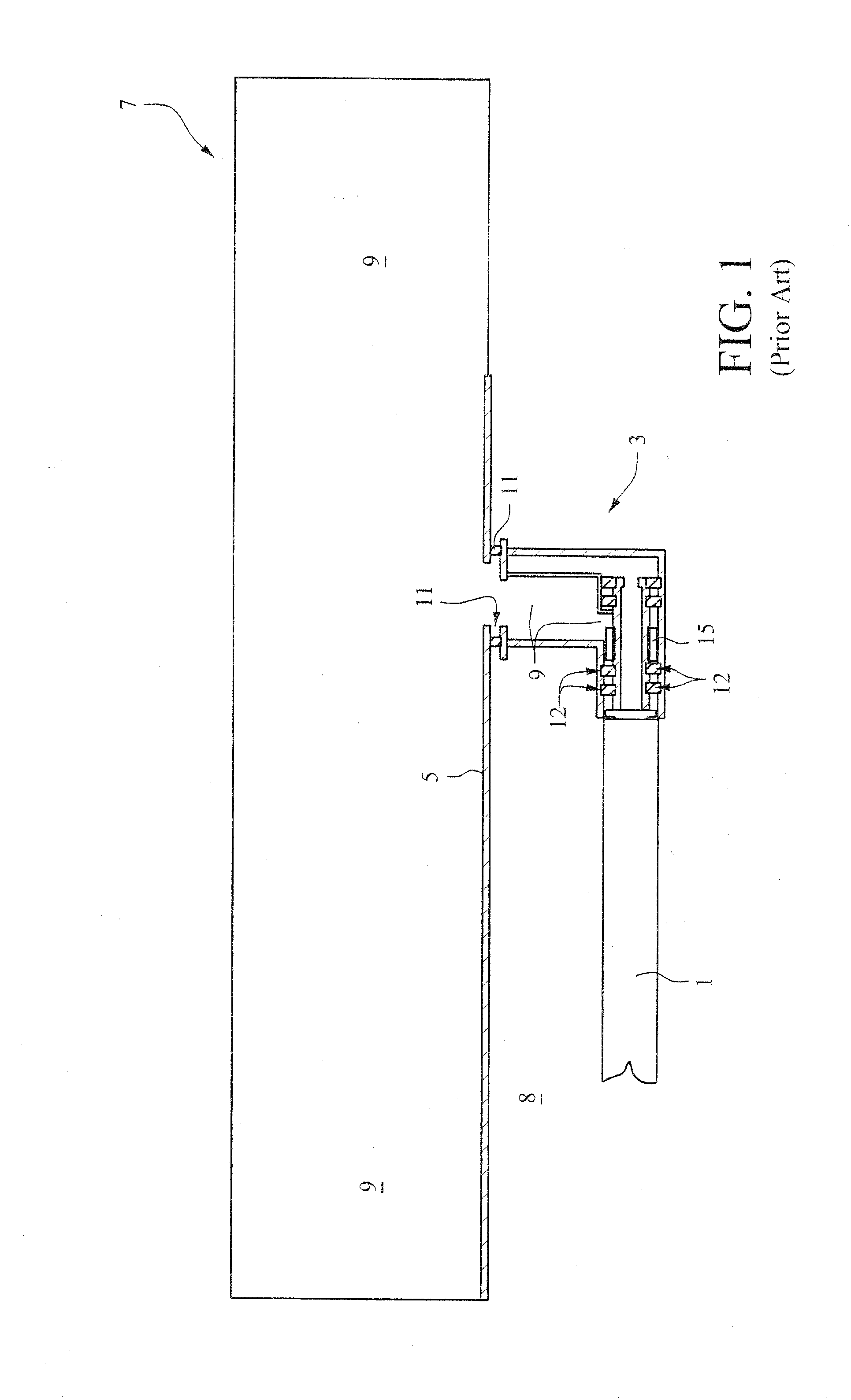
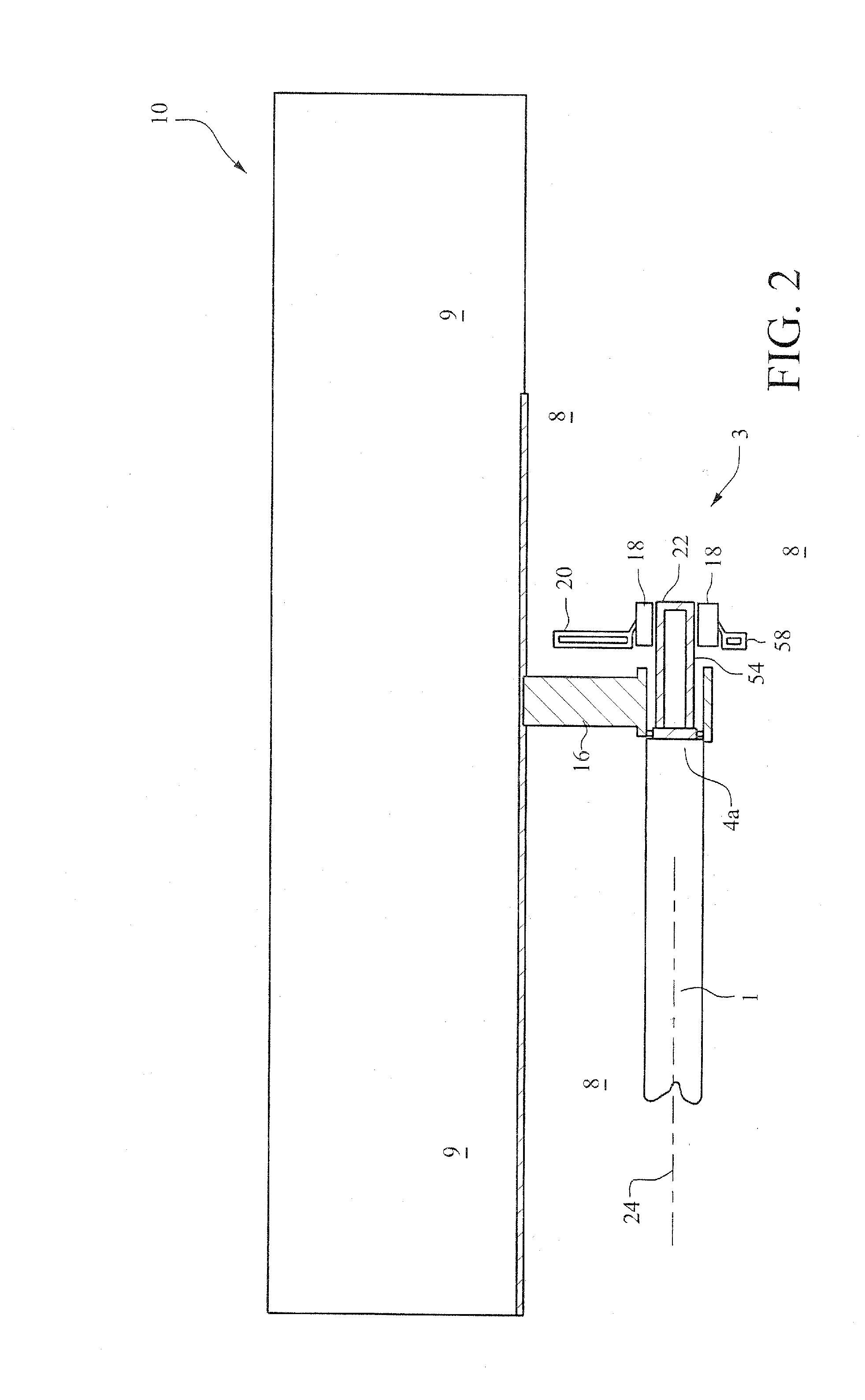
[0014]FIG. 2 is a side plan view of a rotating sputtering target and endblock. The endblock 4 is for a cathode revolver that is to be placed in a sputtering apparatus prior to sputtering operations, and then utilized in the sputtering apparatus during sputtering operation. FIG. 2 illustrates that the rotating cylindrical magnetron target 1 is supported at one end by an endblock 4 designed according to an example embodiment of this invention. And FIG. 3 is a cross sectional view of the endblock 4 of FIG. 2. The endblock 4 may be supported by and / or attached to a wall and / or ceiling 5 of a sputtering chamber 8 in a sputtering apparatus 10 via an endblock support 16. In other preferred embodiments, the endblock 4 may be mounted on and supported by a cathode revolver via support 16 for selective use in sputtering apparatus such as the cathode rev...


PUM

PropertyMeasurementUnit
lengthaaaaaaaaaa
electrical poweraaaaaaaaaa
pressureaaaaaaaaaa

Abstract

An endblock for a rotatable sputtering target, such as a rotatable magnetron sputtering target, is provided. A sputtering apparatus, including one or more such endblock(s), includes locating the electrical contact(s) (e.g., brush(es)) between the collector and rotor in the endblock(s) in an area under vacuum (as opposed to in an area at atmospheric pressure).

Description

[0001]Example embodiments of this invention relate to an endblock for a rotatable sputtering target such as a rotatable magnetron sputtering target. A sputtering apparatus design, including an endblock design, includes locating the electrical contact(s) (e.g., brush(es)) between the collector and rotor in an area under vacuum (as opposed to in an area at atmospheric pressure) which has been found to provide for significant advantages.BACKGROUND AND SUMMARY OF THE INVENTION[0002]Sputtering is known in the art as a technique for depositing layers or coatings onto substrates such as glass substrates. For example, a low-emissivity (low-E) coating can be deposited onto a glass substrate by successively sputter-depositing a plurality of different layers onto the substrate. As an example, a low-E coating may include the following layers in this order: glass substrate / SnO2 / ZnO / Ag / ZnO, where the Ag layer is an IR reflecting layer and the metal oxide layers are dielectric layers. In this exam...

Claims


Application Information

Patent Timeline
Patent Type & Authority Applications(United States)
IPC IPC(8): C23C14/34H01J37/34
CPCC23C14/34H01J2237/332H01J37/3411H01J37/32816H01J37/3405H01J37/3417H01J37/3435H01J37/3497H01J37/342H01J37/34
Inventor GALAN, GILBERTUSELDING, JEAN-PHILIPPECOMANS, GUYSCHLOREMBERG, MARCEL
Owner GUARDIAN GLASS LLC
Why Eureka
Try Eureka