Compact aluminium heat exchanger with welded tubes for power electronics and battery cooling

a technology of heat exchanger and welded tube, which is applied in the direction of manufacturing tools, electrochemical generators, lighting and heating apparatus, etc., can solve the problems of high internal pressure leakage risk, inflexible design, and increased cost involved in machining accurate micro-channels from flat aluminum workpiece plate material with the size and complexity of the required flow path, so as to achieve further improvement of heat exchanger performance and reduce weight

Inactive Publication Date: 2015-07-16
GRANGES ALUMINUM
View PDF9 Cites 46 Cited by
  • Summary
  • Abstract
  • Description
  • Claims
  • Application Information

AI Technical Summary

Benefits of technology

[0028]Use of the heat exchanger having welded aluminum tubes with fin-insert allows scalability since different high frequency welded aluminum tubes can be dimensioned depending on the heat load or foot print of power electronics devices. The use of heat exchanger according to the invention for thermal management of any heat radiating component is suitable in one of hybrid and electrical vehicle.
[0029]Thermal performance of the heat exchanger may be further improved by the use of additional external fins, separating the tubes (see FIG. 2, 3). These fins are brazed onto at least some of the tube carrying flat surfaces.
[0030]The heat exchanger according to the invention provides reduction of its weight and a possibility to make a long-life corrosion design.

Problems solved by technology

The cost involved in machining accurate micro-channels from flat aluminum work-piece plate material increases substantially with size and complexity of the required flow paths.
The press molded plates are brazed with an intermediate plate providing a risk for leakage at high internal pressures.
The electronic components are usually mounted in contact with the cooling tubes via a ceramic plate and heat-conductive grease, a costly process and an inflexible design which suffers from being prone to corrosion.
However, this method of corrosion protection of tubes also causes undesirable Zn segregation in fillets.
Thus although this approach can protect the tube of also inevitably accelerate fillet corrosion.
These extruded cooling tubes forming the heat sink have relatively thick inner fins due to the extruding process requirements and therefore rather heavy (require more material).
Extruded tubes cannot be made with very thin walls which mean that the weight and cost for the heat exchanger increases.
There are also limitations regarding the freedom of design in order to be able to produce multiport extruded tubes, since there are requirements as of minimum web thickness to the height.
This design does not allow minimizing the material consumption and making a heat exchanger with a thinner intermediate walls and reduced weight.
Due to material formability requirements, the drawn cup design cooling tubes according to the prior art U.S. Pat. No. 7,571,759, FIG. 6, require fully soft braze clad materials which in turn are prone to core erosion.
The fin insert used for drawn cup design tube does not provide the optimal coolant flow.
This is difficult to achieve by known drawn cup type tubes with a thin outside plates that shall withstand high internal liquid pressure which will deform the outside tube shell.
Therefore the best flatness required for the efficient heat transfer cannot be achieved by this known type of drawn cup flat tubes.

Method used


Image

  • Compact aluminium heat exchanger with welded tubes for power electronics and battery cooling
  • Compact aluminium heat exchanger with welded tubes for power electronics and battery cooling
  • Compact aluminium heat exchanger with welded tubes for power electronics and battery cooling

Examples


Embodiment Construction

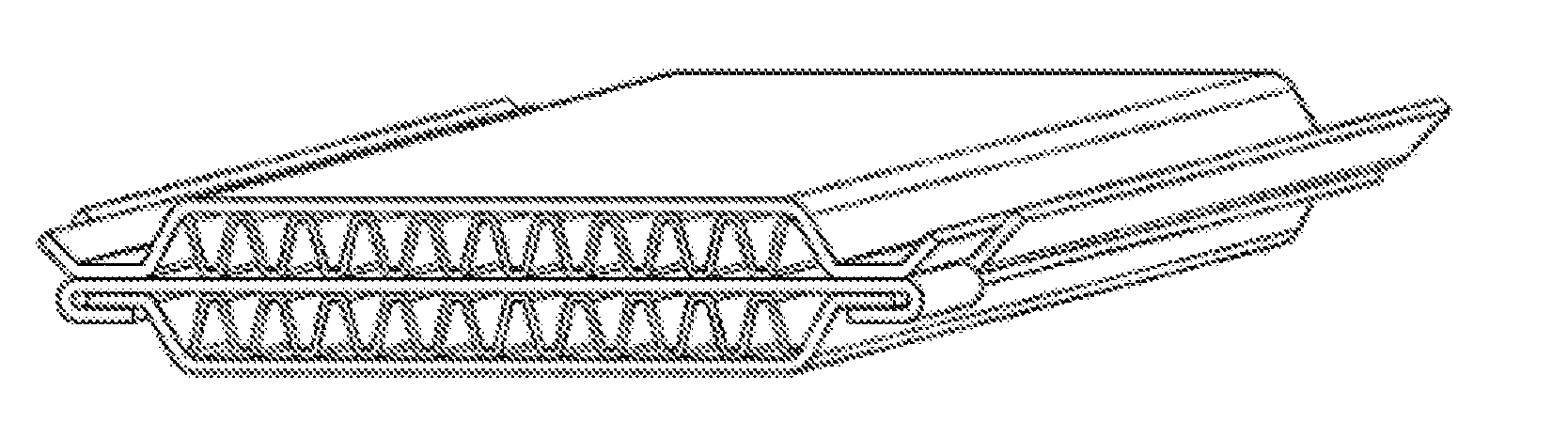
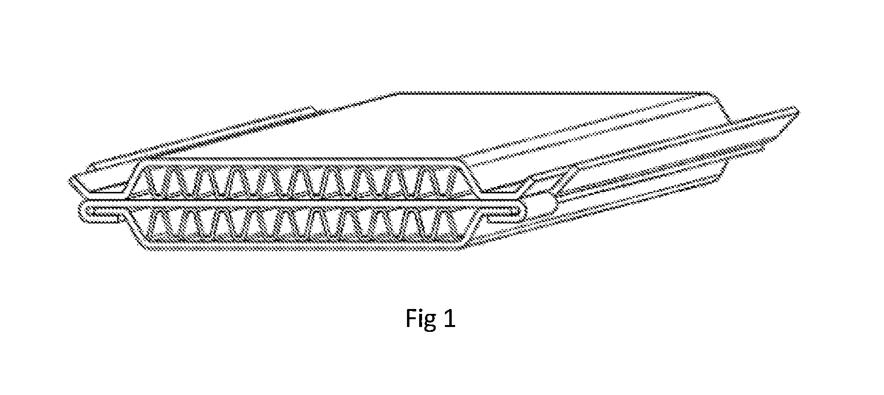
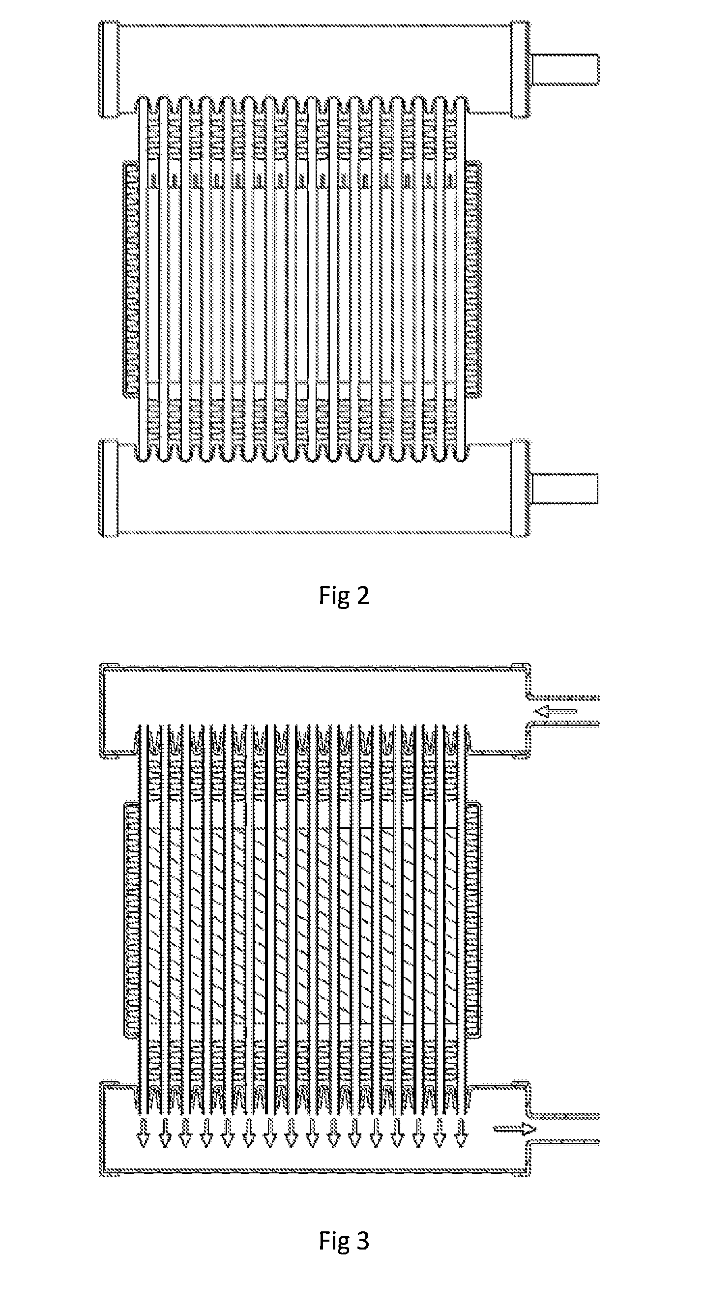
[0038]A so called heat sink module or a heat exchanger 20 as illustrated in FIG. 2, 3 is manufactured by assembling a number of flat tubes 3 manufactured from a metal sheet 11 by bending the sheet to a tubular form to form a sleeve, interconnecting the adjacent sheet edges by high frequency welding or any other suitable welding method forming a weld joint 12, the formed sleeve is pressed to form a flat cooling tube 3. Such flat welded cooling tubes 3 are particularly suitable and made for use into the heat exchanger 20 according to the invention. The heat exchanger 20 according to the invention is particularly suitable for thermal management of any heat radiating component s 5, 6 used in one of hybrid and electrical vehicle.

[0039]The weld joint (12) is preferably situated at the smaller dimension side 14, 14′ of the flat cooling tube 3 to minimize the leakage risks. The tubular component is pressed to approximate the flat tube shape of a bit larger size than a pre-formed fin insert ...


PUM

PropertyMeasurementUnit
Raaaaaaaaaaa
thicknessaaaaaaaaaa
thicknessaaaaaaaaaa

Abstract

Compact aluminum heat exchanger manufactured from welded flat tubes with internal and/or external fins for cooling of power electronic devices and/or battery cells. The fin insert is prefabricated and inserted into the flat tubes for facilitating of flow turbulence and thus heat dissipation and have fins with undulating or wavelike shape manufactured by sampling or corrugating. Flat tubes are bent and welded along their length on their smaller side facilitating mechanical strength of the tubes. Tubes are manufactured from a core alloy containing 0.3 to 1.8 wt % Mn, 0.25-1.2 wt % Cu, ≧0.02 wt % Mg, ≧0.01 wt % Si, ≧0.05 wt % Fe, ≦0.2 wt % Cr, balance aluminum and unavoidable impurities up to 0.05 wt %. Fin inserts are manufactured from aluminum alloy comprising Mn 0-3 wt %, Fe 0-1.5 wt %, Cu 0-1.5 wt %, Mg 0-1.5 wt %, Si 0-1.0 wt %, Zn 0-4 wt %, Ni 0-1 wt % and Zr, Ti, Cr V 0-0.3 wt % each.

Description

TECHNICAL FIELD[0001]The invention relates to a heat exchanger or a cooler suitable for thermal management of electronic components or battery cells that generate heat. The invention is particularly suitable as a heat exchanger for electric power train in a hybrid electric vehicle (HEV) or electrical vehicle (EV) but also applicable in other technical areas for cooling various electric components.BACKGROUND AND DESCRIPTION OF THE PRIOR ART[0002]In order to ensure reliability of power electronic devices in hybrid electric vehicles, heat generated from power electronics assembly need to be dissipated. The substrate of power electronic devices typically has three layers; an etched metal track which forms electrical connections of a circuit, an intermediate layer, i e a plate of electrical insulating material of ceramic type, and a metal plate so called a heat spreader which is connected to the assembly to facilitate spreading heat and provide mechanical support. An alternative is an ex...

Claims


Application Information

Patent Timeline
Patent Type & Authority Applications(United States)
IPC IPC(8): F28D1/03B23P15/26F28F3/02
CPCF28D1/0366B23P2700/10B23P15/26F28F3/025F28D1/0391F28D15/0266H01F27/085H01F27/105H01M10/625H01M10/6551H01M10/6557H01M10/613F28F3/027F28F21/084F28D2021/0029H01M10/6556F28D1/0316F28D2021/0028H01F27/18Y10T29/49378Y10T29/49393Y02E60/10F28D2021/0043
Inventor DESIKAN, SAMPATHHOUSE, XUMEIJERS, STEVEN
Owner GRANGES ALUMINUM
Why Eureka
Try Eureka