Heat Exchanger

a technology of heat exchanger and heat exchange medium, which is applied in the direction of indirect heat exchanger, stationary tubular conduit assembly, light and heating apparatus, etc., can solve the problems of increased pressure drop, non-uniform heat exchange, and reduced heat exchange efficiency of heat exchanger, so as to achieve convenient operation, avoid dead heat exchange area, and improve heat exchange

Active Publication Date: 2015-07-16
ZHENHAI PETROCHEM JIANAN ENG
View PDF10 Cites 3 Cited by
  • Summary
  • Abstract
  • Description
  • Claims
  • Application Information

AI Technical Summary

Benefits of technology

[0009]Preferably, the spherical body further comprises an auxiliary platform surrounding the core. In aid of the auxiliary platform, the operation becomes convenient, and a dead area for heat exchange is avoided forming on the bottom of the spherical body.
[0010]Preferably, the large opening of each connector has an external surface for matching a peripheral surface of each convex head, thus enabling the heat transfer medium to flow more smoothly.
[0011]Compared with the prior art, in the present invention, owing to additionally providing the convex heads, the opening end of each convex head is enlarged as required, so that the axial dimension of each convex head can be increased under the same condition. In this way, the space at the ends of the casing of the heat exchanger may be enlarged, thereby providing a space large enough to accommodate the construction personal and test personal to carry out welding and testing operations therein. Therefore, such improvement creates conditions for two-side welding, so that the casing can be made of clad steel plate material or adopts build-up technology, and the material of the casing may be selected from chrome-molybdenum steel which is not suitable for one-side welding. That is to say, the selection range of the material of the casing of the heat exchanger becomes wider and the design and manufacture of the equipment becomes more reliable, thereby largely extending the application fields of the heat exchanger. Meanwhile, due to larger space and axial distance of the improved ends of the convex heads, the heat transfer medium passages may be formed on the convex heads. In this way, on one hand, a buffer area is provided for the flow of the heat transfer medium, so that the heat transfer medium passages flows more smoothly, multiphase medium distribution is achieved along the cross-section of the casing, the pressure field and the velocity field become more uniform, the heat exchange efficiency of the heat exchanger is improved significantly, and the pressure drop of the heat transfer medium passages is reduced; on the other hand, baffles and check rings may be mounted inside the convex heads as required to reduce the impact force of the heat transfer medium passages to the inlet; meanwhile, auxiliary devices such as flow guide plates and distribution rings may be arranged to further ensure the sufficient heat exchange of the heat exchange area inside the casing. With the use of the heat exchanger provided by the present invention, the temperature of the material flow when discharged from the outlet may be approximate to the required temperature, thereby omitting the subsequent heating devices such as a heating furnace and reducing the running cost. Therefore, this heat exchanger is worthy of popularization and application in the current high-temperature high-pressure hydrogenation devices, hydrocracking and hydrofining devices, and reforming and chemical refining equipment (for example, with aromatic).

Problems solved by technology

Consequently, when the heat transfer medium enters the casing, on one hand, a dead area is likely to form at the convex head, and on the other hand, bias flow of the heat transfer medium, non-uniform flow resistance and inconsistent flow velocity are likely to occur in an effective heat exchange area of the casing, directly resulting in non-uniform heat exchange, decreased efficiency of the heat exchanger and increased pressure drop.
Apparently, the use of such a heat exchanger will inevitably causes the whole system huge, and also increases the initial investment cost and the running cost in the future.
Second, due to the limited space at the ends of the heat exchanger, auxiliary devices such as flow guide plates and check rings can not be additionally provided in this space, that is to say, the flow form of the casing side medium can not be changed, so that the heat exchange efficiency of the heat exchanger can not be improved effectively.
Third, particularly, with a heat exchanger with such end structure, the welding between the cylinder and the convex heads can be performed on only one side because there is no space large enough to accommodate construction personnel at the ports of the casing, influencing the selection of material for the heat exchanger.
For example, in the case that the casing is made of clad steel plate material and a surfacing structure, or, in the case that the material of the casing is selected from chrome-molybdenum steel which is not suitable for one-side welding, it is difficult to manufacture a heat exchanger due to this conventional structure, thereby seriously influencing the design development and extensive application of the heat exchanger.
Fourth, at the end of welding, the testers are still unable to access the ends of the casing to carry out inspection and nondestructive testing.
Furthermore, it is quite difficult to take protective measures against sensitization of the stainless steel core during the heat treatment.
As such, during the future maintenance of the equipment, the maintenance personnel are still unable to access the casing to do maintenance, so maintenance in the future is also quite inconvenient.

Method used


Image

  • Heat Exchanger
  • Heat Exchanger
  • Heat Exchanger

Examples


embodiment 1

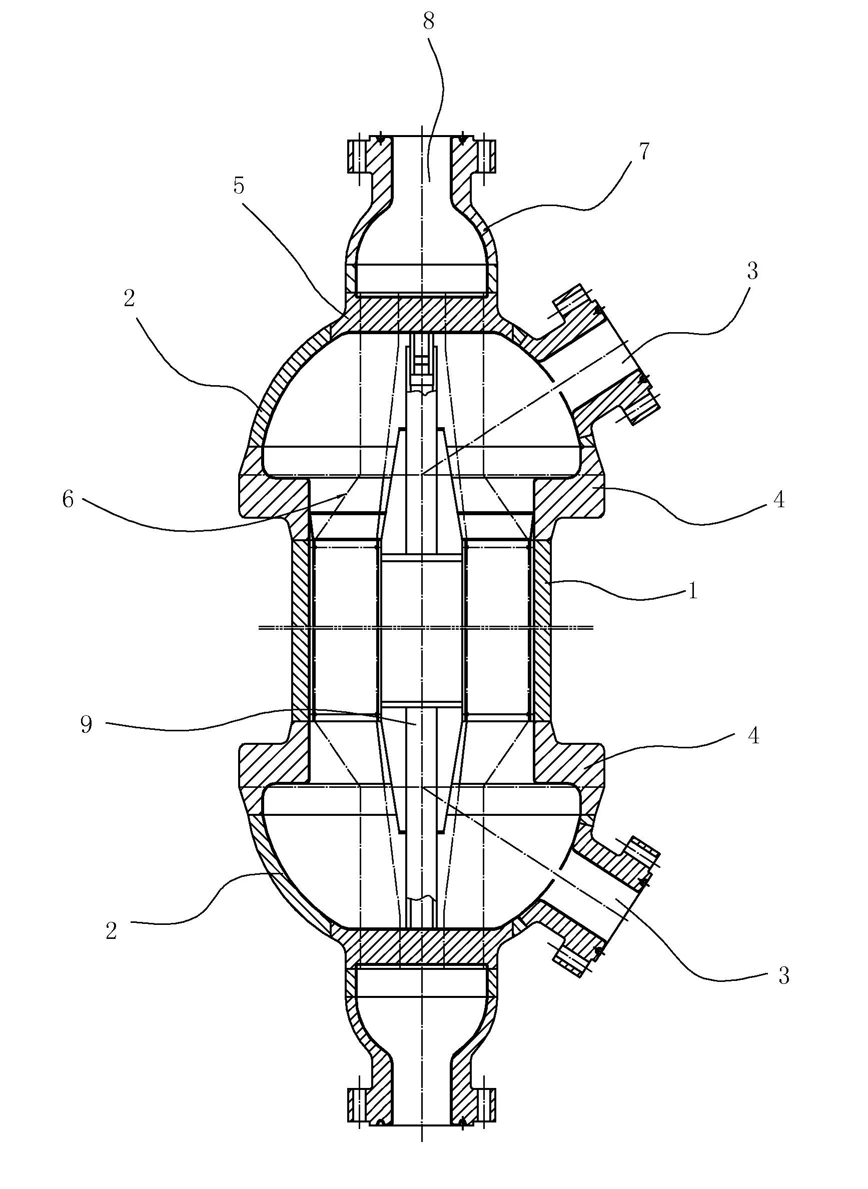
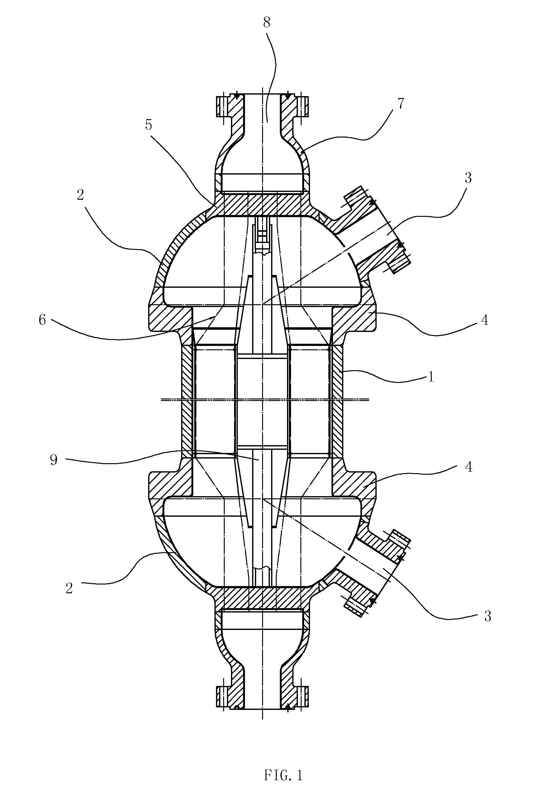
[0019]As shown in FIGS. 1-3, a heat exchanger comprise a casing, a core 6 with two ends disposed inside the casing, each end of the core 6 supported by a tube plate 5 on each convex head, a central cylinder 9 disposed in the center of the core, and two heat transfer medium passages 3 formed on the casing; the casing has a cylinder 1 and two convex heads 2, and the tube plates, the core and the central cylinder 9 are all of conventional configurations; the main improvement is to provide two connectors 4, each connector having two openings with different diameters.

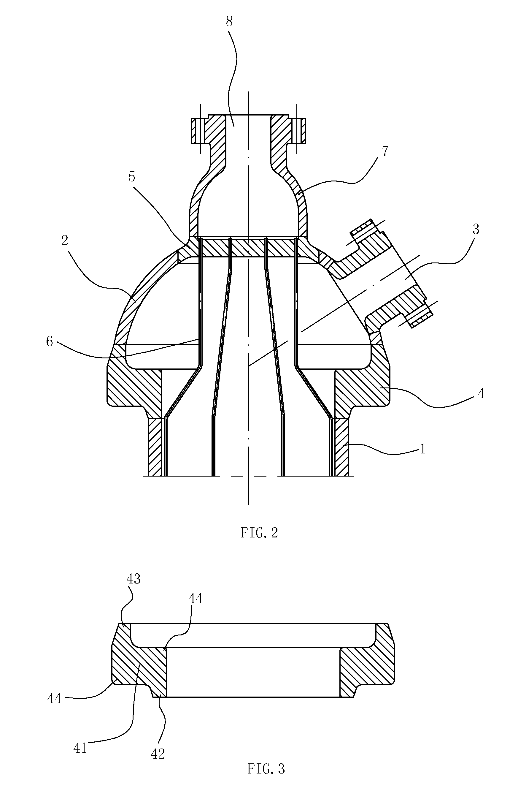
[0020]In this embodiment, each connector 4 comprises an annular body 41 with an internal circular edge having a first thickness and an external circular edge having a second thickness, each connector has a large opening 43 and a small opening 42, the internal circular edge and the external circular edge of each annular body 41 surround the small opening 42 and the large opening 43 respectively; each convex head is connected ...

embodiment 2

[0024]As shown in FIG. 4, the Embodiment 2 differs from the aforementioned Embodiment 1 in that each connector 4 comprises an annular body with an internal circular edge and an external circular edge, the internal circular edge and the external circular edge of each annular body surround the small opening and the large opening respectively, and smooth transition surface A is respectively formed on the internal circular edge and the external circular edge of each annular body. Such a configuration is applicable to the working condition of low pressure, thereby meeting the requirements of different working conditions.

embodiment 3

[0025]As shown in FIG. 5, the Embodiment 3 differs from the aforementioned Embodiment 1 in that each connector 4 comprises a tubular body B having a third thickness connected to a spherical body C having a fourth thickness, and a joint between the tubular body and the spherical body has a thickness greater than the third thicknesses and the fourth thickness of each connector 4. Such a structure is applicable, as used in a heat exchanger with a smaller-diameter cylinder, to the working condition of higher pressure.

[0026]In order to avoid forming a dead area on the bottom of the spherical body, the spherical body further comprises an auxiliary platform 10 surrounding the core. Meanwhile, the auxiliary platform brings convenience to the operations of the construction personnel and test personnel.


PUM


Abstract

A heat exchange, which includes a casing having a cylinder; two connectors respectively attached to one end of the cylinder through the small opening; two convex heads respectively connected through the opening end to the large opening of a connector; a core disposed inside the casing; and two heat transfer medium passages. In this way, the space at the ends of the casing of the heat exchanger may be enlarged, thereby providing a space large enough to accommodate the construction personal and better working environment for two-side welding and future maintenance and wider selection range of material of the casing of the heat exchanger; a buffer area is provided for the flow of the heat transfer medium, and the auxiliary like baffles may be mounted inside the convex heads as required to further improve the heat exchange efficiency and reduce the cost.

Description

RELATE APPLICATIONS[0001]This application is a national phase entrance of and claims benefit to PCT Application for a heat exchanger, PCT / CN2013 / 000306, filed on Mar. 18, 2013, which claims benefit to Chinese Patent Application 201210072963.3, filed on Mar. 19, 2012. The specifications of both applications are incorporated herein by this reference.FIELD OF THE INVENTION[0002]The present invention relates to a heat exchanger, in particular to a heat exchanger with non-detachable casing and core, which is applicable to high-temperature high-pressure hydrogenation devices, hydrocracking and hydrofining devices, and chemical refining equipments for reforming and aromatic hydrocarbons.DESCRIPTION OF THE PRIOR ART[0003]As common heat exchange equipment, as shown in FIG. 6, a heat exchanger includes a core 6′ and a casing, which may be in detachable connection with each other or designed into a non-detachable structure as required. Each end of the casing of a non-detachable heat exchanger ...

Claims


Application Information

Patent Timeline
Patent Type & Authority Applications(United States)
IPC IPC(8): F28D7/10
CPCF28D7/10F28F9/02F28D7/16F28D7/005F28F2009/029F28D7/00F28F9/00
Inventor ZHANG, XIAN'ANWANG, JIANLIANGHU, XINGMIAOLIU, LIJIANGLI, JUNJIE
Owner ZHENHAI PETROCHEM JIANAN ENG
Why Eureka
Try Eureka