Projection image display device

Active Publication Date: 2015-07-16
MITSUBISHI ELECTRIC CORP
View PDF5 Cites 14 Cited by
  • Summary
  • Abstract
  • Description
  • Claims
  • Application Information

AI Technical Summary

Benefits of technology

The patent aims to provide a device that can be placed indoors while maintaining a constant operating temperature for the semiconductor laser elements. The device's size and load capacity can be minimized while still keeping the operating temperature constant.

Problems solved by technology

However, promoting higher-luminance of the projection image display devices including the lamp light sources as described above is difficult in terms of an increase in heat generation and noise as well as an increase in size of a cooling structure and a power supply, and furthermore the wider range of color reproduction and the longer life are also difficult to be achieved.
Particularly, in a case where the light source elements are the semiconductor laser elements, an efficiency of light emission increases as the operating temperature decreases, and on the other hand, as the operating temperature increases, the efficiency of light emission decreases and an increase in crystal defects also progresses.
Moreover, an increase in heat generation corresponding to an increase in a non-radiative transition accompanied by the progression may further cause a temperature rise of a light-emitting element and accelerated decline of its light-emitting capability may occur.
In addition, a shortening of life may progress rapidly.
Furthermore, no matter how high or low an operating temperature is, a wavelength of an output light changes correspondingly to the operating temperature, whereby the original color and the image cannot be projected.
However, an air-cooled cooling is generally used for exhaust heat of the Peltier device, and a heat pipe, a heat sink, a fan, and the like in large size are needed to achieve a sufficient cooling capability by the air-cooled cooling for high output power, resulting in problems that a size of the device and noise by the fan increase.
A loss of power by the Peltier device is large, and thus it is conceivable that power consumption is large and efficiency is poor.
Moreover, a cooling technique using a water cooling is another cooling technique, but due to a temperature differential between an upper stream and a lower stream, maintaining the operating temperature of the plurality of semiconductor laser elements constant is difficult.
However, a volume of cooling air for the optical element group is unbalanced, and thus it is difficult to maintain the operating temperature constant.
The technique disclosed in Japanese Patent Application Laid-Open No. 2009-222869 also requires a large fan for cooling, resulting in problems that a size of the device and noise by the fan increase.
Thus, size of a space for installing the projection image display device and load capacity thereof lead to a problem, resulting in an increase in cost of installation.
Moreover, it is a problem that noise caused by upsizing of the fan or the compressor also increases.

Method used


Image

  • Projection image display device
  • Projection image display device
  • Projection image display device

Examples


first preferred embodiment

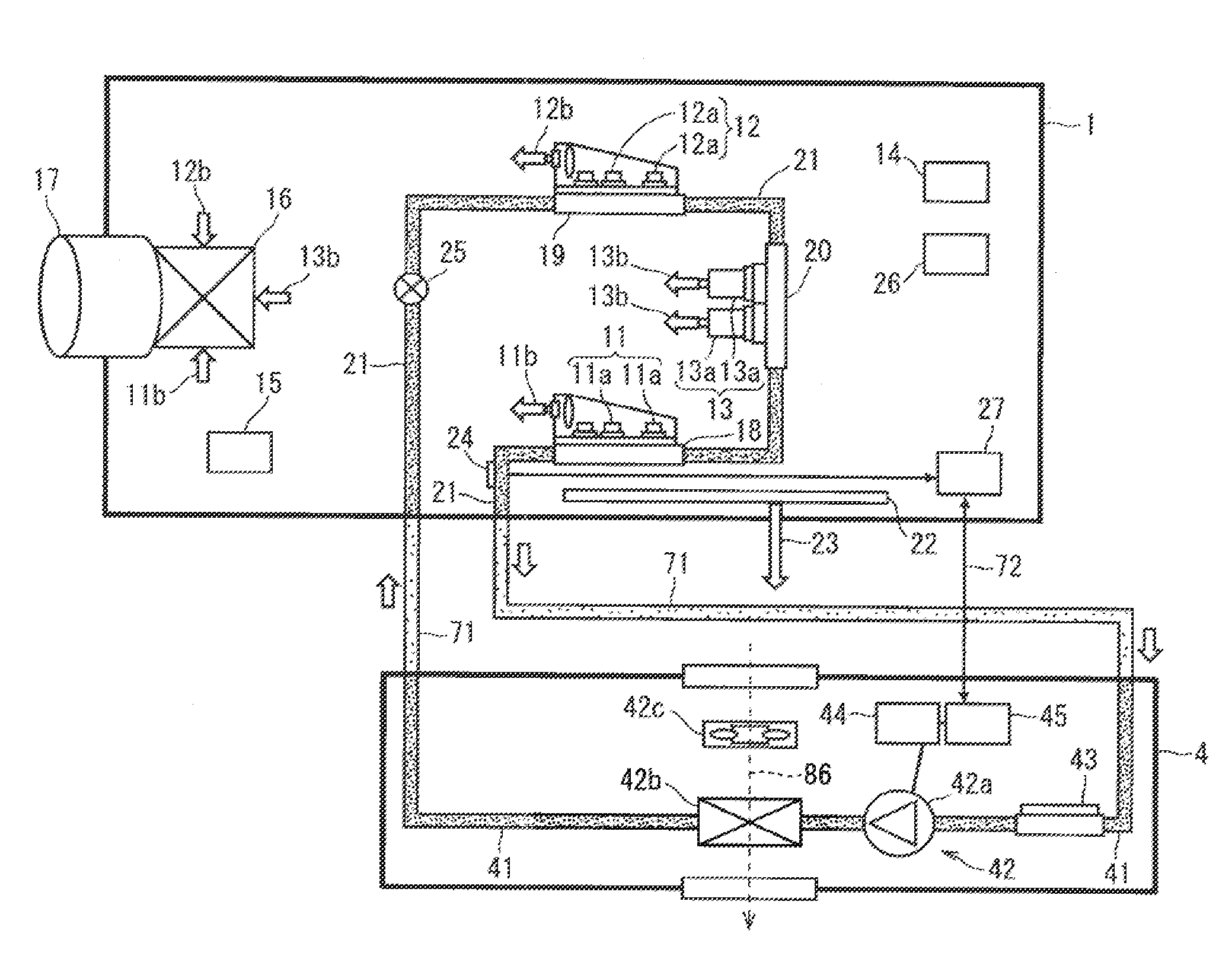
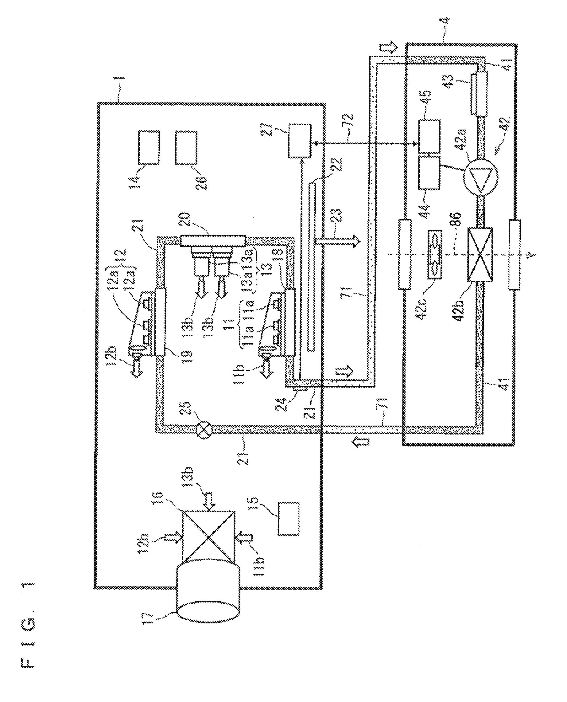
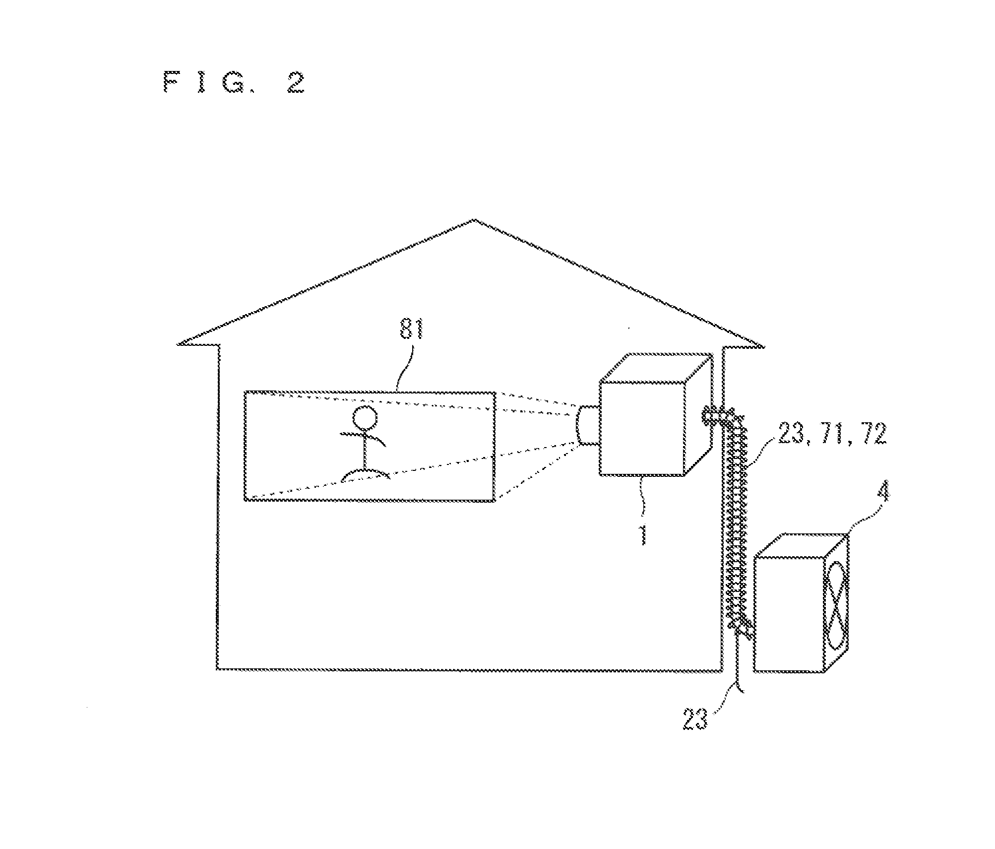
[0022]FIGS. 1 and 2 are diagrams showing configurations of a projection image display device according to a first preferred embodiment of the present invention. The projection image display device (hereinafter, referred to as a “projector”) is a device that projects an image (projection light) onto a screen 81. As shown in FIGS. 1 and 2, the projector includes an indoor unit 1 to be located indoors and an outdoor unit 4 to be located outdoors.

[0023]The indoor unit 1 is a unit that projects the above-mentioned image. The indoor unit 1 according to the first preferred embodiment includes R, G, B laser clusters 11, 12, 13, a laser drive circuit 14, an image processing circuit 15, an optical combining part 16, a projection lens 17, R, G, B laser heat sinks 18, 19, 20, a first refrigerant piping 21, a saucer 22, a drain pipe 23, a temperature control sensor 24, an electronic expansion valve 25, a power circuit 26 supplying power used for structural components of the indoor unit 1, and a ...

first modification

[0054]In the configuration of the first preferred embodiment, the main control circuit 27 may also control the electronic expansion valve 25, to thereby finely adjust the cooling for the R, G, B laser heat sinks 18, 19, 20 by the electronic expansion valve 25. With this configuration, response speed of temperatures in the R, G, B laser heat sinks 18, 19, 20 can be improved.

[0055]Moreover, in the configuration of the first preferred embodiment, the G laser heat sink 19, the B laser heat sink 20, and the R laser heat sink 18 are connected in the stated order and in series through the first refrigerant piping 21. However, this is not restrictive, and the R, G, B laser heat sinks 18, 19, 20 may be connected in parallel through the first refrigerant piping 21. The plurality of electronic expansion valves 25 (herein, three) controlled by the main control circuit 27 may be provided to correspond to the R, G, B laser clusters 11, 12, 13 on one-to-one basis. The plurality of the temperature ...

second modification

[0058]The indoor unit 1 according to the first preferred embodiment includes the temperature control sensor 24 provided to the first refrigerant piping 21 in downstream side from the R, G, B laser heat sinks 18, 19, 20. However, this is not restrictive, and the indoor unit 1 may include temperature sensors detecting temperatures of joints (pn junctions) of the semiconductor laser elements 11a, 12a, 13a, instead of the temperature control sensor 24. The main control circuit 27 may control the cooling by the cooling device 42 to maintain the temperatures detected by the temperature sensors at predetermined temperatures.

[0059]With this configuration, even if the amount of heat generated by the semiconductor laser elements 11a, 12a, 13a changes as luminance of the semiconductor laser elements 11a, 12a, 13a changes, the operating temperatures of the semiconductor laser elements 11a, 12a, 13a can be maintained constant. Therefore, a change in wave lengths of the red laser light 11b, the g...


PUM


Abstract

A projection image display device includes an indoor unit to be located indoors and an outdoor unit to be located outdoors. The outdoor unit includes a second refrigerant piping that forms a loop refrigerant path in combination with a first refrigerant piping, a cooling device, and a cooling control circuit that controls cooling for R, G, B laser heat sinks by the cooling device. The indoor unit includes a main control circuit that communicates with the cooling control circuit to control the cooling by the cooling device.

Description

BACKGROUND OF THE INVENTION[0001]1. Field of the Invention[0002]The present invention relates to a projection image display device that projects an image onto a screen and more particularly to cooling of the projection image display device.[0003]2. Description of the Background Art[0004]Conventionally, many projection image display devices (projectors) adopt lamps as light sources for generating light beams of three primary colors. These projection image display devices separate white light emitted from the lamps, into the three primary colors of red (R), green (G), and blue (B) by means of a dichroic mirror, and after modulating the three primary colors by image information and combining them by a combining prism, the projection image display devices project them onto a screen through a projection lens, to thereby display an image.[0005]On the other hand, demands for higher-luminance (higher output power), a wider range of color reproduction, and a longer life have been increasing ...

Claims


Application Information

Patent Timeline
IPC IPC(8): G03B21/16G03B21/00G03B21/20
CPCG03B21/16G03B21/005G03B21/2013G03B21/2033H01J17/28
Inventor KURIAKI, MAKOTO
Owner MITSUBISHI ELECTRIC CORP
Why Eureka
Try Eureka