Method for producing metallic iron

a technology of metallic iron and production method, applied in the direction of gas current separation, electric furnace, furnace, etc., can solve the problems of increasing energy and difficult use in electric furnaces or blast furnaces, and achieve the effect of efficient separation, efficient collection and efficient separation

Inactive Publication Date: 2015-07-23
KOBE STEEL LTD
View PDF5 Cites 9 Cited by
  • Summary
  • Abstract
  • Description
  • Claims
  • Application Information

AI Technical Summary

Benefits of technology

[0061]According to the first invention and the second invention, metallic iron can be efficiently collected.
[0062]In detail, according to the first invention, a reduced product containing metallic iron and slag, that is discharged from the movable hearth type heating furnace, is crushed by applying impact, so the metallic iron and slag are efficiently separated. Also, the reduced product containing metallic iron and slag that is discharged from the movable hearth type heating furnace is separated into coarse particulate material and fine particular material using a sifter, and processed according to granularity, so the metallic iron and slag are efficiently separated. That is to say, while metallic iron can be efficiently collected using a separator (e.g., sifter, magnetic separator, etc.), the metallic iron can be collected even more efficiently by combining pulverizing and a separator.
[0063]According to the second invention, discharged matter including metallic iron, slag, and hearth covering material, that is discharged from the movable hearth type heating furnace is suitably crushed or pulverized, so metallic iron can be efficiently collected from the discharged matter.

Problems solved by technology

However, the blast furnace method and ITmk3 method involve heating at high temperatures, and accordingly exhibit increased energy if a great amount of gangue component is present in the material.
For example, a reduced product, obtained by reducing by heating an agglomerate including iron ore having a gangue component of 9% (total amount of SiO2 and Al2O3) and coal having ash content of 10%, contains 15% slag (total amount of SiO2 and Al2O3), so use in either of an electric furnace or blast furnace is difficult.

Method used


Image

  • Method for producing metallic iron
  • Method for producing metallic iron
  • Method for producing metallic iron

Examples


first modification

[First Modification]

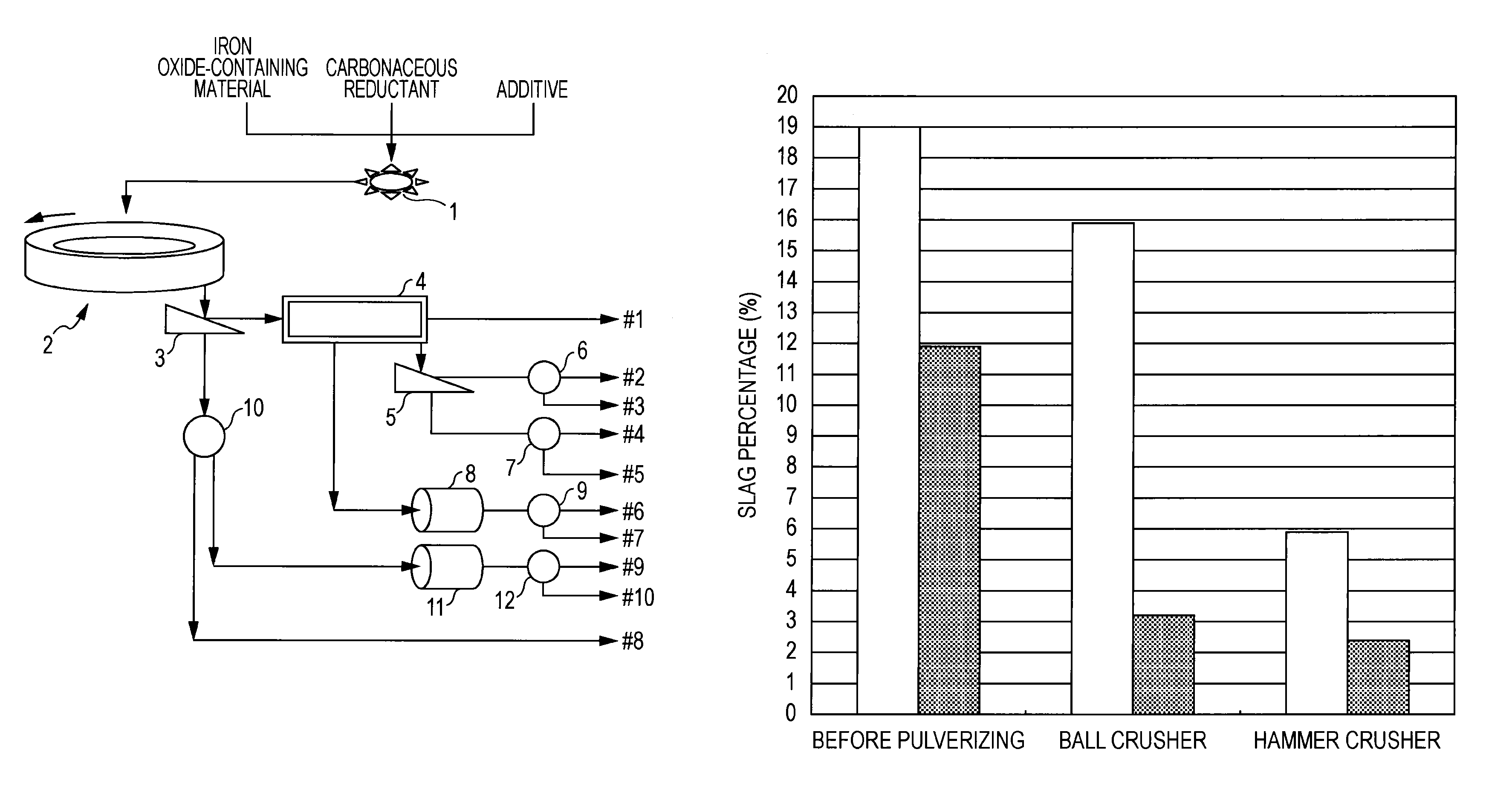
[0397]When heating the agglomerate in a movable hearth type heating furnace, there are cases where the metallic iron melts on the hearth and joins with nearby metallic iron and forms large clumps. In the same way, there are cases where slag melts on the hearth and joins with other nearby slag and forms large clumps. Slag forming large clumps is crushed during discharge from the heating furnace and subsequent handling, and thus is broken down into finer pieces. However, the metallic iron forming large clumps is not broken down into finer pieces, and remains in large clumps. Supplying the large clumps of metallic iron to the crushing process places a load on the crusher, leading to marked wear on the crusher.

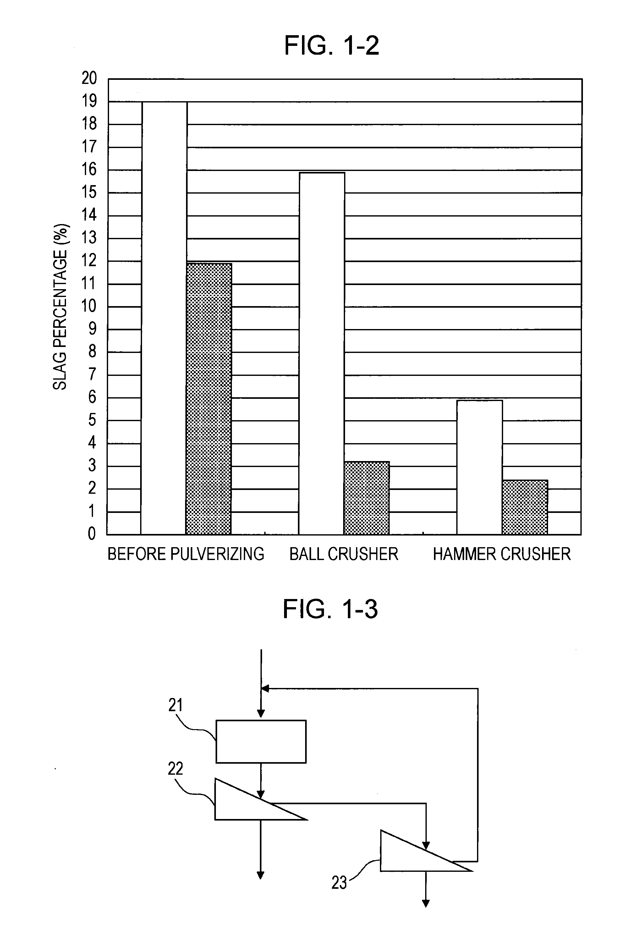
[0398]Accordingly in the first modification, as illustrated in FIG. 3-3, the reduced product which is the discharged matter from the movable hearth type heating furnace 101 is screened using the sifter c having a sieve opening of 15 to 20 mm (105 in FIG. 3-3). ...

second modification

[Second Modification]

[0399]When the agglomerate is heated in a heating furnace at 1300° C. or hotter, hearth covering material such as carbonaceous particles, heat-resistant particles, and so forth may be laid on the hearth of the heating furnace for protection. The suitable granularity of the hearth covering material is said to be 0.5 to 3 mm, meaning that the material is small particles. This hearth covering material is discharged from the heating furnace along with the reduced matter after having heated the agglomerate. Accordingly, the medium particles which have passed through the sifter c in the above-described screening process c (undersieve c) include the hearth covering material.

[0400]Accordingly, in the second modification, as illustrated in FIG. 3-3, the reduced product discharged from the movable hearth type heating furnace 101 is screened using the sifter c having a sieve opening of 15 to 20 mm (105 in FIG. 3-3), and the medium particulate material which has passed thro...

third modification

[Third Modification]

[0401]In the third modification, the medium particulate matter collected as undersieve c on the sifter b may be sorted at the magnetic separator (107b in FIG. 3-3), thereafter supplied to the crusher 102 via an unshown path, and the magnetically attractable substance crushed by application of impact, as described above. The collecting efficiency of metallic iron obtained by crushing the magnetically attractable substance can be improved by sorting the magnetically non-attractable substance by a magnetic separator beforehand.

[0402]Also, the medium particulate matter collected as undersieve c on the sifter b may be sorted at the magnetic separator (107b in FIG. 3-3), the magnetically attractable substance thereafter supplied to the pulverizer (108b in FIG. 3-3), pulverized, and select the magnetically non-attractable substance by the magnetic separator (107e in FIG. 3-3) beforehand, thereby improving the collecting efficiency of metallic iron (104b in FIG. 3-3) obt...


PUM

PropertyMeasurementUnit
densityaaaaaaaaaa
temperatureaaaaaaaaaa
grain sizeaaaaaaaaaa

Abstract

The first purpose of the present invention is to provide a method for producing metallic iron, whereby, in the production of metallic iron by heating an agglomerate, which comprises an iron oxide-containing material and a carbonaceous reductant, in a movable hearth type heating furnace, metallic iron can be efficiently collected from a reduced product containing metallic iron and a slag, said reduced product being obtained by heating the agglomerate. The method for producing metallic iron according to the first embodiment of the present invention comprises: a step for forming an agglomerate of a mixture which comprises an iron oxide-containing material and a carbonaceous reductant; a step for introducing the obtained agglomerate into a movable hearth type heating furnace and reducing the same by heating; a step for crushing a reduced product containing metallic iron and a slag, said reduced product being discharged from the movable hearth type heating furnace, using an impact crusher; and a step for selecting and collecting the metallic iron using a separator.

Description

TECHNICAL FIELD[0001]The present invention relates to a method for producing metallic iron by heating an agglomerate, obtained by forming an agglomerate of a mixture including iron oxide-containing material and a carbonaceous reductant, in a movable hearth type heating furnace.BACKGROUND ART[0002]Methods for producing metallic iron from iron oxide-containing material such as iron ore or the like are classified into several types, depending on the method of separating gangue component included in the iron oxide-containing material.[0003]An iron making process in a consistent way, using a blast furnace, is the method which enables the greatest amount of metallic iron to be produced. This method involves using high-grade iron ore including little gangue component, or using an iron oxide-containing material consisting of iron ore of which the grade of iron has been improved by concentration, which are heated in a blast furnace to be reduced and melted, and separated into the gangue comp...

Claims


Application Information

Patent Timeline
Patent Type & Authority Applications(United States)
IPC IPC(8): C21B11/08B03C1/30C22B5/10C21B13/10C22B1/16C22B1/24B03C1/02B07B9/00
CPCC21B11/08B03C1/02B03C1/30B07B9/00B03C2201/20C22B1/16C22B1/24C22B5/10C21B13/10B07B15/00C21B13/0046C21B13/0086C21B13/105C21B13/14C22B1/2406C22B1/245Y02P10/20
Inventor SUGIYAMA, TAKESHIHARADA, TAKAOSHIINO, JUNICHIMIMURA, TSUYOSHIIIJIMA, KATSUYUKIOKA, TAKANORI
Owner KOBE STEEL LTD
Why Eureka
Try Eureka