Jet shower device

a technology of shower device and jet, which is applied in the direction of valve housing, multiple way valve, mechanical apparatus, etc., can solve the problems of affecting the comfort level of use, the water outflow rate of the water outflow unit is relatively small, and the cost of solar water heaters is high. achieve the effect of reducing the cost of use, facilitating operation and facilitating us

Active Publication Date: 2015-07-23
GUANGZHOU SEAGULL KITCHEN & BATH PROD
View PDF5 Cites 12 Cited by
  • Summary
  • Abstract
  • Description
  • Claims
  • Application Information

AI Technical Summary

Benefits of technology

[0009]Therefore, the technical problem to be solved in the present invention is how to provide a jet shower device with higher usage comfort level, lower usage cost and operation convenience.

Problems solved by technology

The water tank of this structure type bears pressure from tap water, has relatively larger water outflow rate and better usage comfort level, however, the water tank of this structure type is required to bear water pressure of up to 7 MPa, in addition, a heat pipe structure needs to be further provided inside the tank, and there are also requirements for relatively high sealing effect, and relatively thicker material, thus causes relatively higher cost of the solar water heater.
However, because the mounting height of the water tank is limited by the architectural structure, it is generally difficult for the solar water heater of this type of structure to provide relatively higher water pressure to the water outflow unit, which results in relatively smaller water outflow rate of the water outflow unit and negatively affects the usage comfort level.
However, for the water heater valve disclosed in this patent literature, the opening diameter of its nozzle is constant, and when adjusting inflow rates of cold water and hot water respectively through the cold water flow rate regulating switch and the hot water flow rate regulating switch, if the opening size of the cold water flow rate regulating switch is adjusted to be smaller than the opening size of the nozzle, then the pressure of the working fluid inside the nozzle will be reduced, so as to reduce the jet velocity of the working fluid of cold water, thereby causing weaker effect of hot water pumping, which leads to lower usage comfort level when used in summer.
However, it has the following defects during usage:
When the nozzle is rotated, the needle valve moves with the nozzle, and during this process, there is no relative motion occurred between the nozzle and the needle valve, so that the cross-sectional area of the outlet of cold water is always kept constant, as a result, when the cross-sectional area of the inlet of cold water is smaller than the cross-sectional area of the outlet of cold water, the water pressure of cold water inside the nozzle will be very low, and it will be difficult to achieve better jetting effect, and that, in order to ensure better jetting effect, the needle valve needs to be adjusted at the same time, so as to decrease the cross-sectional area of the outlet of cold water, which requires simultaneous adjustment of the needle valve and the nozzle with increased difficulty of usage, and if the needle valve and the nozzle are not adjusted at the same time, then it is difficult to ensure better water out flowing effect and higher usage comfort level.
It can be understood from the preceding discussion that, how to improve the water mixing valve in order to simultaneously achieve higher usage comfort level, lower usage cost and more convenient operation is a technical problem that is unsolved in the prior art.

Method used


Image

  • Jet shower device
  • Jet shower device
  • Jet shower device

Examples


embodiment 1

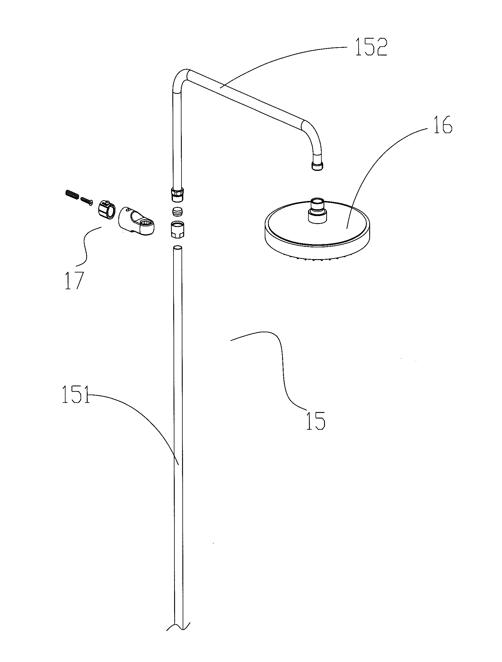
[0054]As shown in FIG. 10 and FIG. 11, this embodiment provides a jet shower device, comprising a water mixer body (A), a jet injection valve (B) and a shower assembly, wherein, the water mixer body (A) has a cold water port (A1), a hot water port (A2) and a mixed water outlet, the jet injection valve (B) has a cold water inlet (B1) and a hot water inlet (B2), the cold water port (A1) is communicated with the cold water inlet (B1), the hot water port (A2) is communicated with the hot water inlet (B2), the volumes of cold water and hot water that flow into the jet injection valve (B) are adjustable by adjusting the opening sizes of the cold water port (A1) and the hot water port (A2), respectively, and the shower assembly has a pipeline 15 communicated with the mixed water outlet of the water mixer body (A) and a sprinkler head 16 communicated with the pipeline 15.

[0055]In this embodiment, the opening size of the cold water port (A1) is adjustable through a cold water regulating swit...

embodiment 2

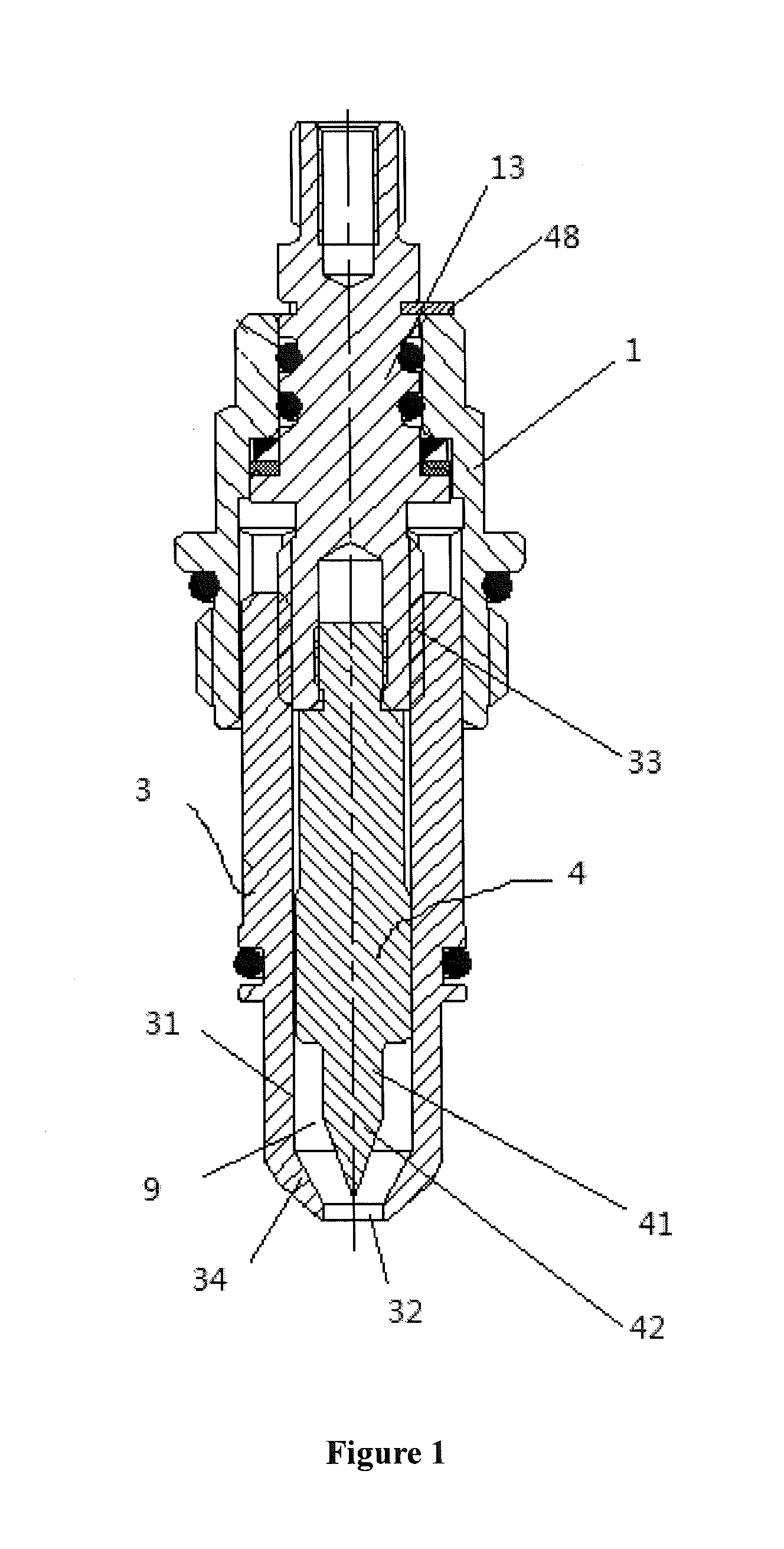
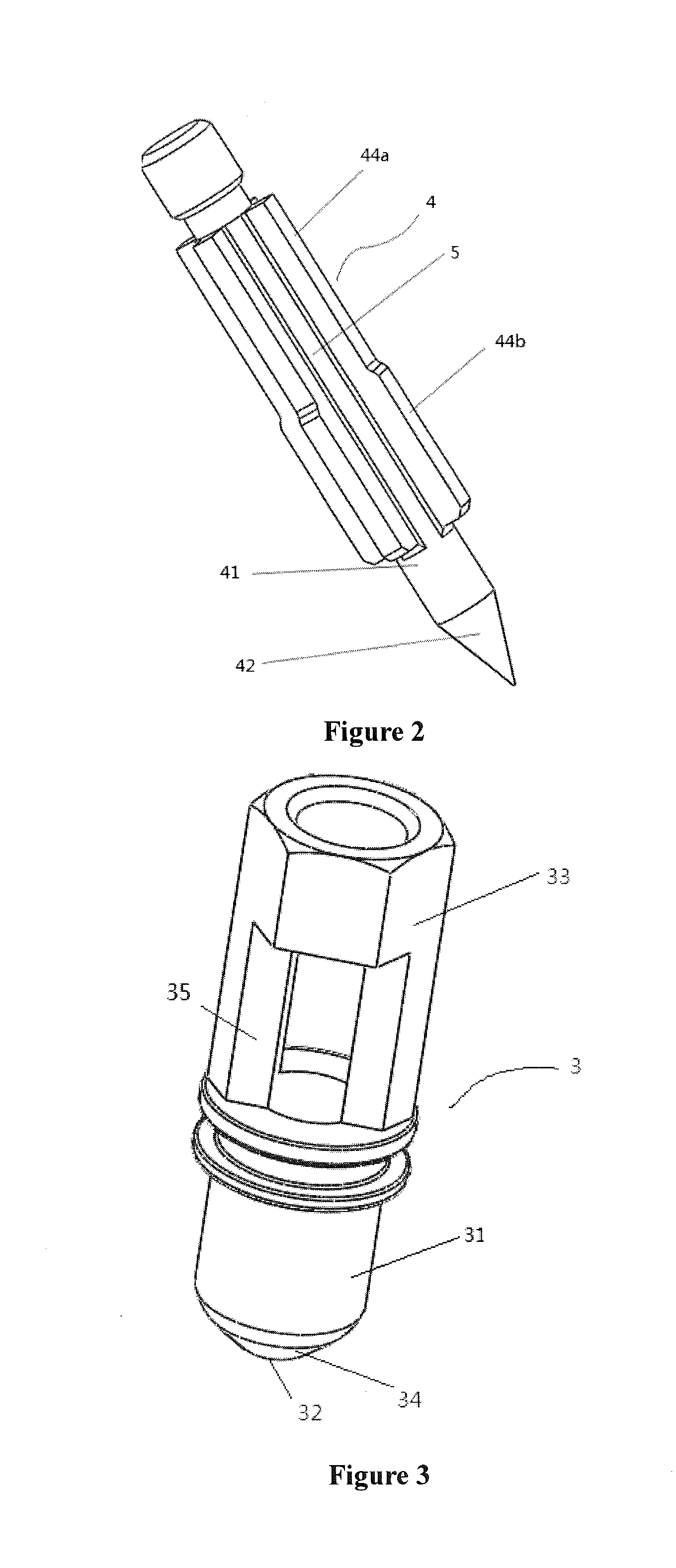
[0075]As shown in FIG. 7, this embodiment provides an improved jet shower device based on Embodiment 1, and the improvement mainly focuses on the fact that the supporting member of the needle 4 employs a different structure. In this embodiment, the supporting member is an annular supporting board 45 formed on the needle body 41, and the annular supporting board 45 is provided with a plurality of flow diversion holes 46 formed thereon and serving as the fluid passage 5. This configuration enables fluent inflow of cold water, and is able to symmetrically support the needle 4.

embodiment 3

[0076]As shown in FIG. 6, this embodiment provides an improved jet shower device based on Embodiment 1, and the improvement mainly focuses on the fact that the supporting member of the needle 4 employs a different structure. In this embodiment, the supporting member is a circular ring 43, the circular ring 43 is connected on the needle body 41 through a plurality of rib strips 40, and each two adjacent rib strips 40 have one fluid passage 5 formed therebetween. This configuration not only ensures fluent inflow of cold water, but also is able to symmetrically support the needle 4.


PUM


Abstract

A shower jet device includes a spray needle arranged in a spray nozzle; a cold water inflow space and a cold water jet outlet formed between the spray nozzle and the spray needle; a hot water inflow space formed between the spray nozzle and a valve body; wherein a cold water inlet respectively in communication with a cold water opening and the cold water inflow space; and a hot water inlet is respectively in communication with a hot water opening and the hot water space.

Description

TECHNICAL FIELD[0001]The present invention relates to a jet shower device, and especially relates to a jet shower device used in a water supply system of a solar water heater, which belongs to the technical field of solar water heaters.BACKGROUND TECHNOLOGY[0002]The solar water heaters of the prior art mainly include the pressure-bearing type and the non-pressure-bearing type.[0003]The operating principle of the pressure-bearing type of solar water heaters is that: tap water flows into the water tank and the heat pipe through a control switch, the heat collecting tube absorbs solar radiation and then transmits thermal energy to the cold water in the heat pipe, so as to circularly heat the water in the water tank, however, as the water tank is an enclosed construction as a whole, during usage it is necessary to open the cold water inlet and utilize the water pressure of the tap water to push out the hot water of the water tank, so as to allow hot water to flow into the water using un...

Claims


Application Information

Patent Timeline
Patent Type & Authority Applications(United States)
IPC IPC(8): E03C1/02F16K11/00B05B1/18
CPCE03C1/025F16K11/00B05B1/185F16K11/0445F16K19/006F16K27/0254F16K27/0263F16K11/044F16K11/207
Inventor YUAN, XUNPINGTANG, ZHIQIANGMAI, XIANXIN
Owner GUANGZHOU SEAGULL KITCHEN & BATH PROD
Why Eureka
Try Eureka