
Projection system and projection-type image display apparatus

a projection system and projection type technology, applied in the field of projection system and projection type image display apparatus, can solve the problems of large diameter of the entrance pupil, increase in cost, and difficulty in ensuring high performance, and achieve the effects of increasing the size of the lens, improving the performance, and relatively compact structur

Active Publication Date: 2015-07-23
SEIKO EPSON CORP
View PDF1 Cites 4 Cited by
  • Summary
  • Abstract
  • Description
  • Claims
  • Application Information

AI Technical Summary

Benefits of technology

The invention provides a long focus zooming projection system that is compact and high performing. It uses a special arrangement of lenses to correct spherical aberrations and reduces the amount of lens movement during focusing. The system is formed of six or seven groups and using a specific movement pattern between them prevents variations in aberrations during a change in setting. Additionally, the system uses a conditional expression to ensure that the focal lengths of the lenses are nearly equal, which further reduces spherical aberrations and prevents an increase in lens size.

Problems solved by technology

Using such a projection system to form a long-focus system undesirably results in a large diameter of the entrance pupil.
As a result, it is difficult to ensure high performance.
Further, the diameter of a mechanism in a projector body increases and the diameters of the lenses increase, resulting in an increase in cost.
For example, using the imaging system described in JP-A-2007-157097 as a projection system increases the size of a front lens, the overall length of the projection system, and the diameter of an aspheric lens, resulting in a difficulty in manufacturing, an increase in cost, and other problems.

Method used


Image

  • Projection system and projection-type image display apparatus
  • Projection system and projection-type image display apparatus
  • Projection system and projection-type image display apparatus

Examples


example 1

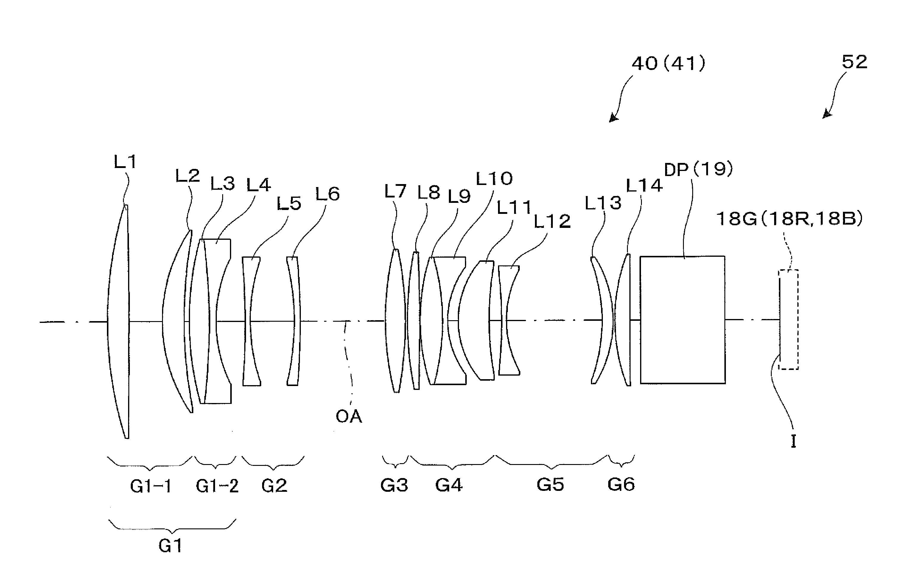
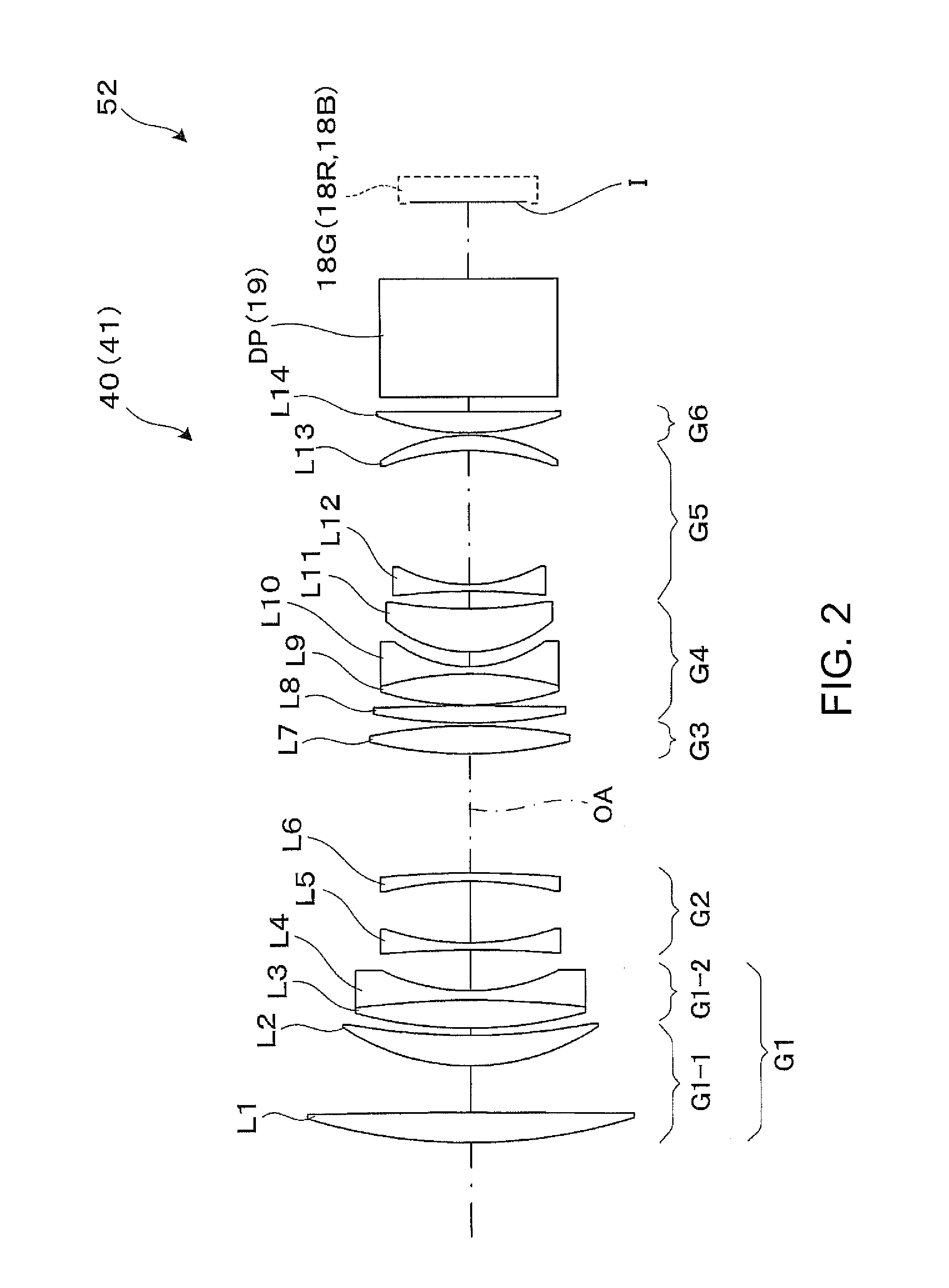
[0065]Table 1 below shows data on lens surfaces that form a projection lens in Example 1. In Table 1 and other tables, “SURFACE NUMBER” means the number of a surface of the lens, “LENS” means the number of the lens, and “GROUP” means the lens group to which the lens belongs. In the tables, for example, “L3 / 4” means a cemented lens formed of the third lens L3 and the fourth lens L4. Further, “INFINITY” means infinite distance.

TABLE 1SURFACENo.LENSGROUPRdndμdSCINFINITYOBJ1L11-1G188.3510.161.846723.82−3630.9215.803L21-1G77.5010.321.487570.54221.73A5L3 / 41-2G146.949.461.487570.56−322.323.201.548145.8768.65B8L52G−395.122.401.672732.2989.8820.9310L62G−124.232.801.784725.711−349.58C12L73G143.559.451.741052.613−178.30D14L84G169.345.801.713053.915−1060.920.2016L9 / 104G100.0610.571.487570.517−113.682.401.672732.21842.604.9819L114G43.5814.571.772549.620146.55E21L125G−221.512.301.603438.02251.1045.2723L135G−81.965.271.531748.824−57.00F25L146G88.177.141.846723.8267446.865.0027DPINFINITY401.516864....

example 2

[0071]Table 5 below shows data on lens surfaces that form a projection lens in Example 2.

TABLE 5SURFACENo.LENSGROUPRdndμdSCINFINITYOBJ1L11-1G291.538.711.846723.82−765.2618.143L21-1G82.9210.211.744044.94325.21A5L3 / 41-2G242.287.981.487570.56−216.815.001.620036.3786.636.288L52G260.283.201.672732.2959.0212.0910L62G−122.532.401.728328.311176.140.6512L72G112.704.281.846723.813320.19B14L83G191.028.861.772549.615−171.24C16L9 / 104G129.529.751.487570.517−157.422.201.688931.21858.922.8319L114G60.739.591.772549.620348.69D21L125G−89.702.401.548145.822103.8524.9623L135G507.268.651.497081.624−83.23E25L146G103.475.481.846723.826401.61527DPINFINITY501.516864.228INFINITY39.04PAINFINITY0.00

[0072]Table 6 below shows zoom data for describing magnification changing action of the projection lens in Example 2 that operates in the wide-angle end setting and the telephoto end setting.

TABLE 6PARAMETERWIDETELEf165.2231.1FNO2.02.6OBJ20 mEFFECTIVE IMAGE CIRCLEφ44DIAMETERω (HALF ANGLE OF VIEW)7.65.4A3.473.47B48.32...

example 3

[0077]Table 9 below shows data on lens surfaces that form a projection lens in Example 3.

TABLE 9SURFACENo.LENSGROUPRdndμdSCINFINITYOBJ1L11-1G284.756.031.846723.825742.2520.003L21-1G78.7812.161.487570.54561.470.205L31-1G82.447.401.487570.56170.06A7L4 / 51-2G151.856.491.487570.58994.9531.647733.8966.94B10L62G−1210.712.91.620036.31162.137.2812L72G−194.952.41.620036.313117.70C14L83G131.846.341.846723.815947.72D16L94G550.084.521.658450.917−424.05E18L105G217.027.331.497081.619−207.640.2020L11 / 125G109.0312.501.497081.621−96.892.501.688931.22264.642.8723L135G65.307.931.744044.924217.98F25L146G−216.543.201.672732.226101.0917.1627L156G−345.924.761.658450.928−118.62G29L167G89.156.591.846723.830458.70531DPINFINITY401.516864.232INFINITY31.12PAINFINITY0

[0078]Table 10 below shows zoom data for describing magnification changing action of the projection lens in Example 3 that operates in the wide-angle end setting and the telephoto end setting.

TABLE 10PARAMETERWIDETELEf140.7197.4FNO1.92.2OBJ17 mEFFECT...


PUM


Abstract

A projection lens is a zoom lens and formed of a first group to an N-th group sequentially arranged from an image enlargement side (that is, screen side), where N is 6 or 7. The first group includes a first A group and a first B group sequentially arranged from the image enlargement side. The first A group is formed of two positive lenses, and the first B group is formed of a cemented lens formed of a positive lens and a negative lens. The second group includes at least two negative lenses. In magnification changing action, at least the first group and the N-th group are fixed, and at least the third group to the (N−1)-th group are moved along an optical axis. In focusing action, the first A group on the image enlargement side in the first group is solely moved along the optical axis.

Description

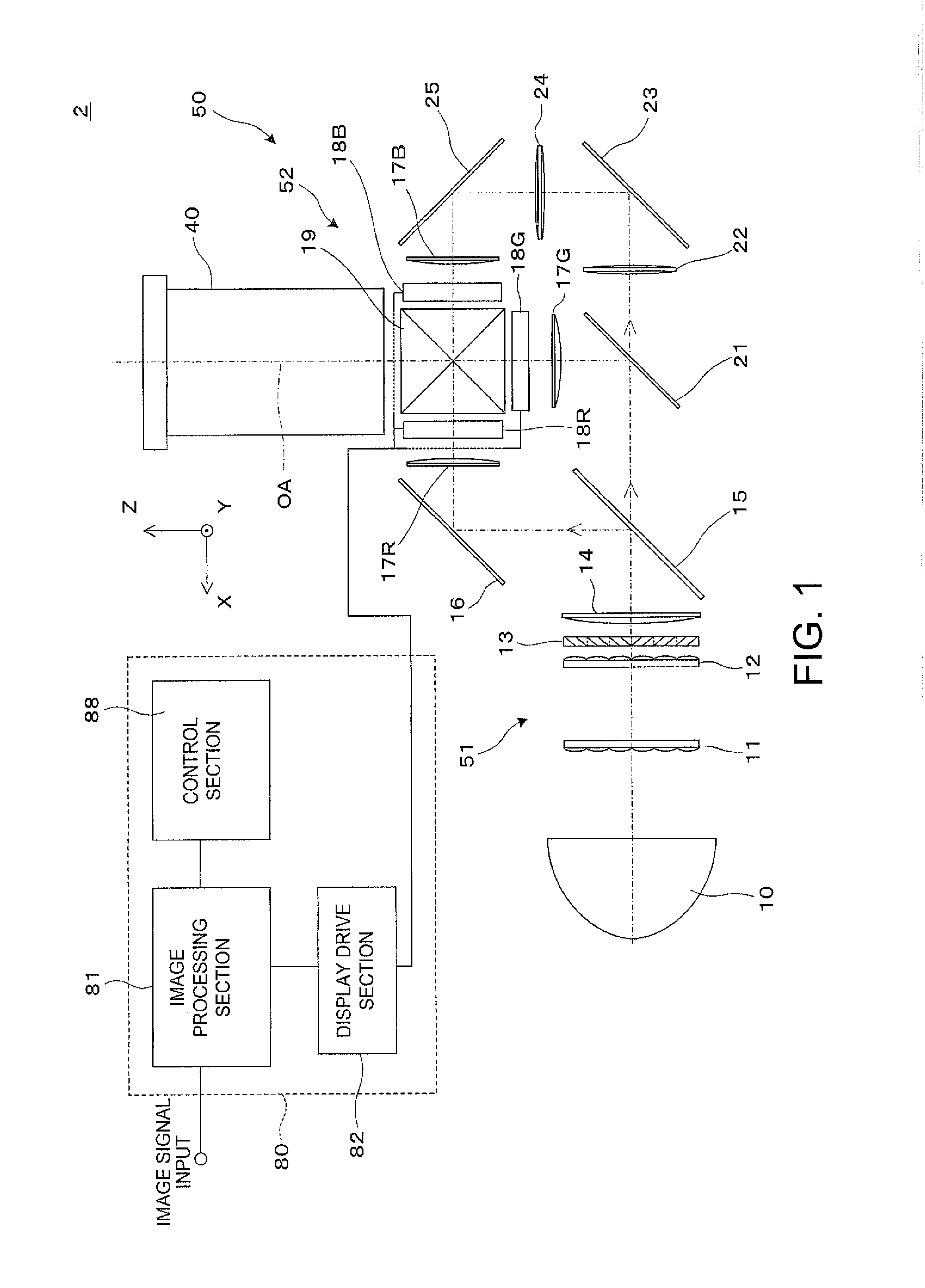
BACKGROUND[0001]1. Technical Field[0002]The present invention relates to a projection system suitable to be incorporated into a projector that enlarges and projects an image formed on an image display device, and also relates to a projection-type image display apparatus into which the projection system is incorporated.[0003]2. Related Art[0004]In recent years, as the luminance and resolution of a projector are increased, a projector can be installed at a wider range of locations, and there is an increasing demand for installation of a projector at a location relatively apart from a screen. To meet the demand, it is necessary to provide a long-focus zoom lens that not only performs projection over a relatively long distance from the screen to meet a specific screen size but also achieves high resolution.[0005]That is, as the luminance of a projector is increased, the projector is increasingly used in an application in which the projector itself is installed at a location apart from a...

Claims


Application Information

Patent Timeline
Patent Type & Authority Applications(United States)
IPC IPC(8): G02B15/167G03B21/14G02B13/16
CPCG02B15/167G03B21/142G02B13/16G02B15/146G02B15/142G02B15/14G02B15/16G02B15/20
Inventor SHIOKAWA, KOJI
Owner SEIKO EPSON CORP
Learn More