Method for integrating an antenna with a vehicle fuselage

a technology of array antennas and fuselages, applied in the field of vehicle stealth technology, can solve the problems of reducing the possibility of physically angling the surface of the aperture away from the threat sector, difficult to handle, and inability to operate within the antenna operational band of broadband array antennas

Active Publication Date: 2015-07-23
SAAB AB
View PDF1 Cites 10 Cited by
  • Summary
  • Abstract
  • Description
  • Claims
  • Application Information

AI Technical Summary

Benefits of technology

[0006]The problem is found to be particularly hard to handle when it comes to small, broadband, array antennas because of impedance differences arising over a broad frequency band, and because a ...

Problems solved by technology

This may be difficult due to physical and mechanical characteristics of the antenna that often contributes to an increased radar cross section.
A frequency selective surface operating within the antenna operational band is not feasible for broadband array antennas due to the large frequency bandwidth of such antennas.
The problem is found to be partic...

Method used


Image

  • Method for integrating an antenna with a vehicle fuselage
  • Method for integrating an antenna with a vehicle fuselage
  • Method for integrating an antenna with a vehicle fuselage

Examples


examples

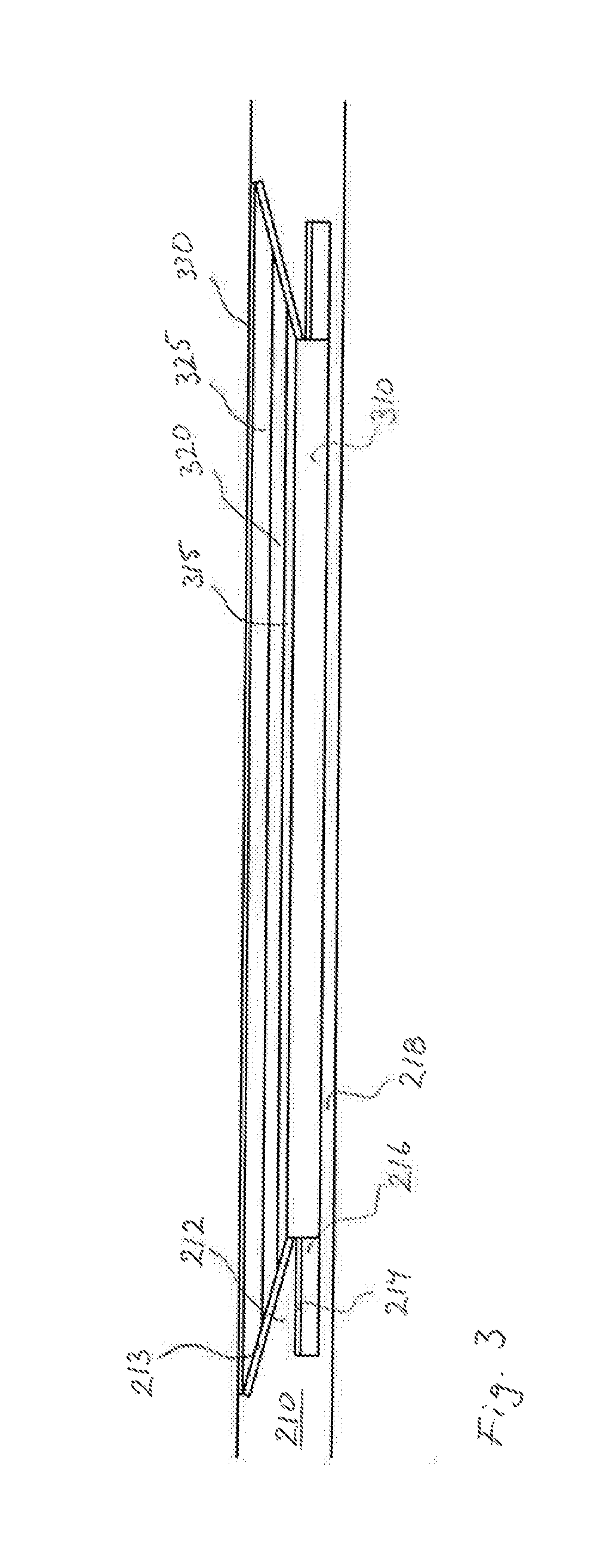
[0064]Particularly good results, or good compromises have been achieved at simulations or tests with the following parameters:[0065]L1: 0.5 to 4 wavelengths at the highest operating frequency of the antenna.[0066]L2: 0.5 to 3 wavelengths at the highest operating frequency of the antenna.

[0067]It has also been found that RCS will be reduced further the longer the transition is made, i.e., with a greater value of the maximum of L1 and L2 the lower the RCS, other parameters unchanged.

[0068]As the transition and the frame surrounds the antenna aperture it will occupy a large area, in particular if maximum of L1 and L2 is large. This may not be acceptable due to limited hull area, which is particularly true for aircraft. This may be a factor limiting maximum of L1 and L2. It has been found that when maximum of L1 and L2 is greater than 3 to 4 wavelengths at highest operational frequency, the further improvement in RCS when maximum of L1 and L2 is increased further is not so pronounced. T...


PUM


Abstract

An antenna frame for reducing radar cross section of a vehicle provided with a flat microstrip patch antenna array comprising a number of microstrip patches arranged in an array pattern, the antenna frame:—being arranged to surround the outer periphery of the flat antenna array—the frame comprising a first conductive sheet;—the first conductive sheet extending from the most peripheral patches and outward in a sloping manner; wherein dielectric and magnetic absorbent material are arranged to improve impedance transition from a point of the antenna to a point on the periphery of the frame, which is also contemplated as adjoining a vehicle fuselage.

Description

TECHNICAL FIELD[0001]The present invention relates to the field of antennas. The invention also relates to the field of vehicle stealth technology. More specifically it relates to the integration of array antennas with the vehicle carrying it, in order to achieve improved stealth characteristics by reducing radar cross section of the combination of antenna and vehicle. In particular it relates to a method and to an antenna frame for this purpose.BACKGROUND ART[0002]The invention relates to the field of integration of an array antenna aperture with a vehicle structure with the intention of lowering vehicle radar cross section. In this field attempts have been made before with varying results.SUMMARY OF THE INVENTION[0003]The invention relates to the field of integration of array antenna apertures with vehicles, in particular with the intention of producing a low vehicle radar cross section. This may be difficult due to physical and mechanical characteristics of the antenna that often...

Claims


Application Information

Patent Timeline
IPC IPC(8): H01Q1/27H01Q17/00H01Q9/04
CPCH01Q1/27H01Q17/00H01Q9/0407H01Q1/3291H01Q21/065
Inventor FORSLUND, OLAHOLTER, HENRIK
Owner SAAB AB
Why Eureka
Try Eureka