
Variable air cooling system for data centers

a cooling system and data center technology, applied in the field of data center cooling system, can solve the problems of large amount of heat generated by computer servers and other large high-performance computer systems, disturbance of integral planning air flow in the under-floor system, and large configuration of hardware components, etc., to achieve high density, low density environment, and energy efficiency

Active Publication Date: 2015-07-23
KYNDRYL INC
View PDF8 Cites 24 Cited by
  • Summary
  • Abstract
  • Description
  • Claims
  • Application Information

AI Technical Summary

Benefits of technology

The invention provides a way to cool high-density and low-density environments with direct air at high efficiency. The system is modular, meaning it can be reconfigured, and it avoids the need for infrastructure investment.

Problems solved by technology

Densely configured hardware components, in particular, computer servers and other large high-performance computer systems, generate a large amount of heat when operating which requires cooling.
Under floor air systems are known which require a raised floor and integral planning Air flow may be disturbed in under floor systems due to cables and other components being placed in the under floor space.
However, the energy efficiency is not good due to the inability to have direct free cooling and the lack of compatibility with existing low density areas.
Even in the standard free cooling systems, controlling the outside air temperature and hygrometry (T&H), the blowing T&H, starting of free cooling, and air mixing unit settings is always a complicate problem.
It requires several control loops interfering each other.

Method used


Image

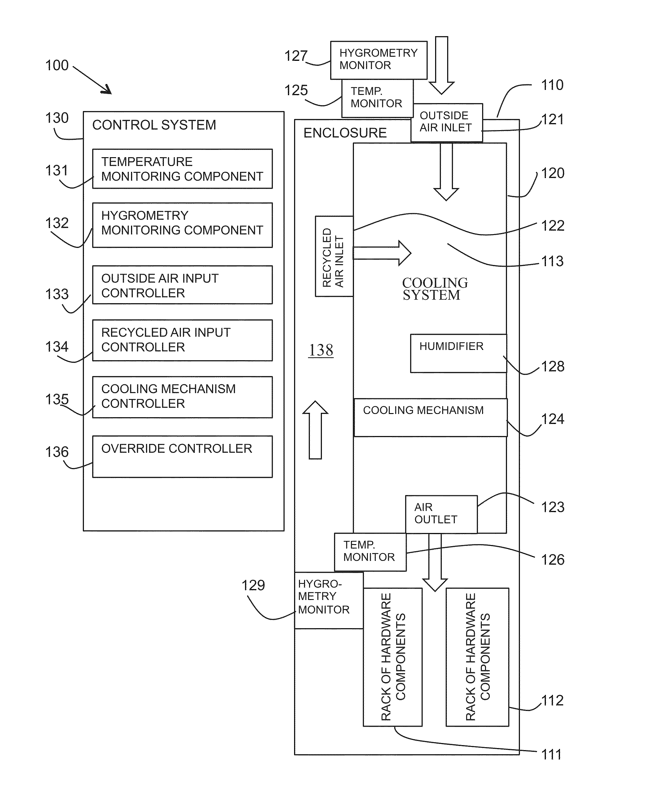
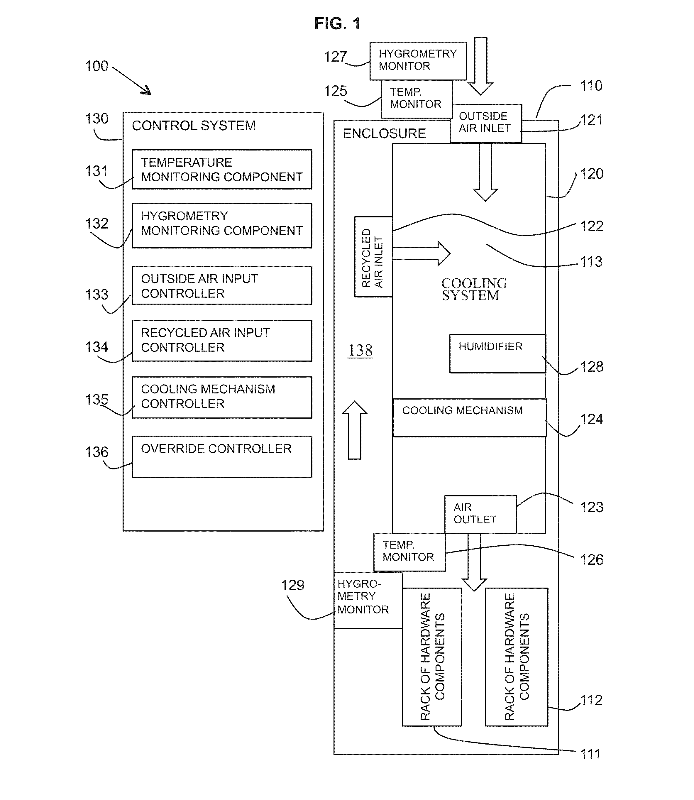
  • Variable air cooling system for data centers
  • Variable air cooling system for data centers
  • Variable air cooling system for data centers

Examples


first embodiment

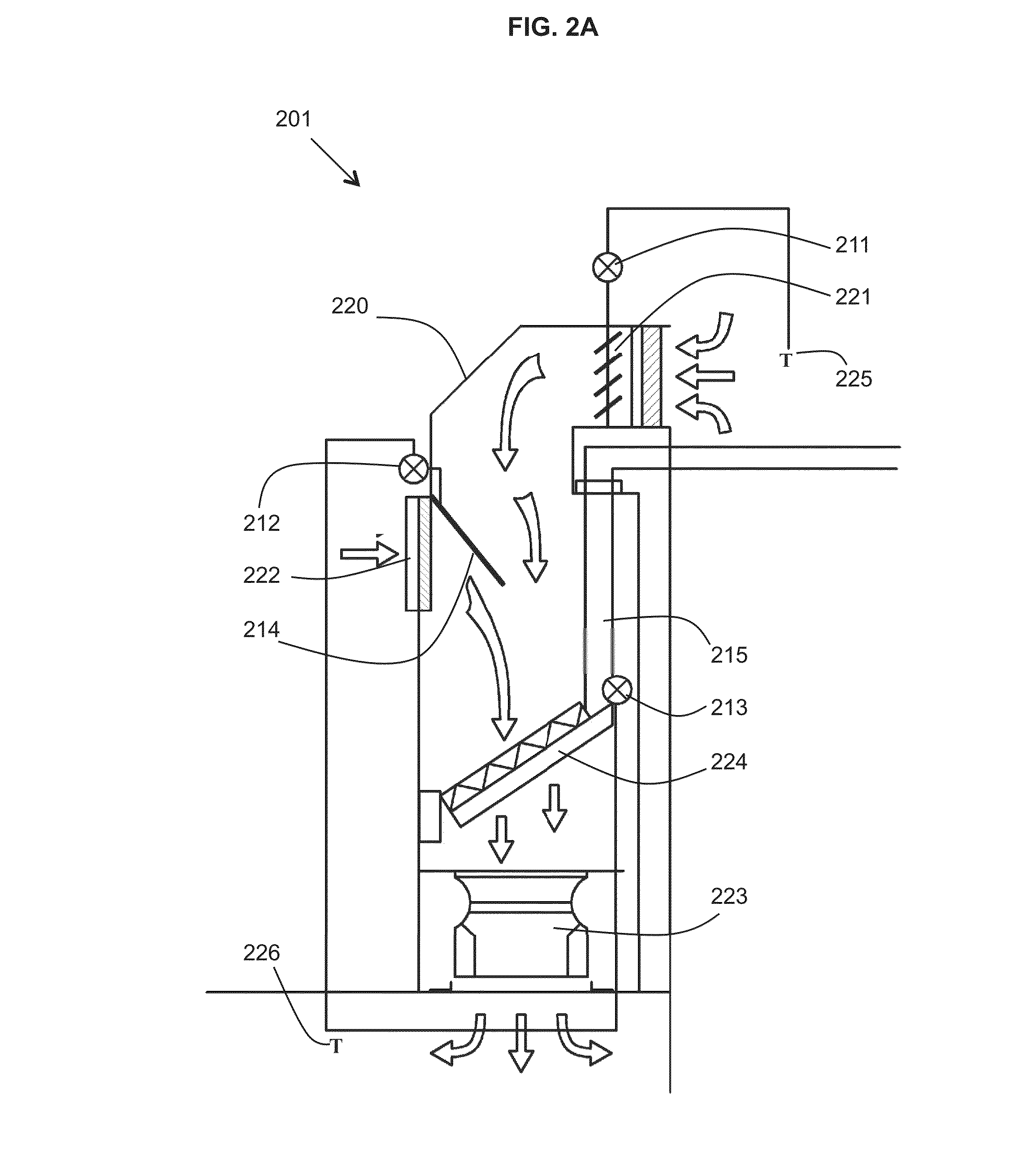
[0057]Referring to FIGS. 2A to 2D, a cooling system is shown in four different temperature operations.

[0058]FIGS. 2A to 2D show a cooling system 220 with an outside air inlet 221 in the form of a outside air shutter with a controller engine 211 and an outside air temperature monitor 225. The cooling system 220 may also include a recycled air inlet 222 with a filter and a recycled air shutter 214 with a controller engine 212. The air shutter 214 in rotation controls the mixing between the air coming from the outside air inlet 221 and the recycled air coming from air inlet 222. The air outlet 223 may be in the form of a fan for sucking air through the cooling system 220 and blowing air out into the enclosure. A blowing air temperature monitor 226 may be provided adjacent the air outlet 223. The cooling system 220 may also include a cooling mechanism 224 in the form of a heat exchanger with a controller engine 213. The cooling mechanism 224 may be fed with cooling water through a pipe ...

second embodiment

[0064]In the second embodiment, a cooling system is provided for independent modular systems, for example, for each pair of data center rows of racks having a cold air aisle between them. Each independent cooling module may intake outside air and mix the outside air with inside air for controlling the temperature of the air using a loopback mechanism. In addition, each module may blow air at variable temperatures in a temperature range to maintain the temperature and humidity of the air in the data center. Ingested outside air may also be treated with a cold vapour generator (for example, a sprinkler or water pulverization system) present in each module.

[0065]Referring to FIGS. 4A, 4B and 4C, three examples are shown of arrangements 401, 402, 403 of the second embodiment of the described cooling system used in a modular system.

[0066]FIGS. 4A, 4B and 4C have common elements as follows. Two racks 411, 412 are shown with a cold aisle 413 between them and hot aisles 414A, 414B on the op...


PUM


Abstract

A method and system for variable air cooling for data centers. The system may include: an enclosure to be cooled suitable for housing hardware components; a cooling system including: a first air input for controllably allowing input of outside air from outside the enclosure; a second air input for controllably allowing input of recycled air from the enclosure; a selectively activatable cooling mechanism; an air output for allowing output of air into the enclosure; a first temperature monitor for monitoring an outside air temperature of air outside the enclosure; a second temperature monitor for monitoring a blowing air temperature of air at the air output; and a control mechanism for controlling an operation of the first air input, the second air input, and the cooling mechanism dependent on a monitored outside air temperature at the first temperature monitor and a monitored blowing air temperature at the second temperature monitor.

Description

TECHNICAL FIELD[0001]The present invention relates to the field of cooling system for data centers and in particular, the invention relates to a variable air cooling system for high density data centers.BACKGROUND[0002]Rack frame mounting systems for hardware components are used in a large number of environments in which multiple hardware components are stacked either vertically or horizontally in an enclosure. Rack frame mounting systems are commonly used in data centers to house computer hardware in dense hardware configurations. For example, the computer hardware may be in the form of servers, storage units, etc. Rack frame mounting systems are also used for hardware systems other than computing systems such as telecommunications, audio, video, entertainment, etc.[0003]Densely configured hardware components, in particular, computer servers and other large high-performance computer systems, generate a large amount of heat when operating which requires cooling. In some situations, ...

Claims


Application Information

Patent Timeline
Patent Type & Authority Applications(United States)
IPC IPC(8): H05K7/20F24F11/00
CPCH05K7/20745H05K7/2079H05K7/20836F24F2011/0075H05K7/20145H05K7/20763F24F2011/0061F24F11/006F24F11/30F24F11/62F24F11/63F24F11/46F24F11/84F24F11/58F24F2140/00F24F11/70
Inventor BAUCHOT, FREDERICCLEMENT, JEAN-YVESLEGRAND, JEAN-MARCROUGEAUX, FRANCOIS-RENE
Owner KYNDRYL INC
Learn More