Inductive sensing including inductance multiplication with series connected coils

Active Publication Date: 2015-07-30
TEXAS INSTR INC
View PDF5 Cites 32 Cited by
  • Summary
  • Abstract
  • Description
  • Claims
  • Application Information

AI Technical Summary

Problems solved by technology

When the target is exposed to the time varying magnetic field, the time varying magnetic field induces eddy currents in the surface of the target, which causes the time varying magnetic field to lose power.
The increase in the magnitudes of the eddy currents causes the time varying magnetic field to lose more power.
One of the disa

Method used


Image

  • Inductive sensing including inductance multiplication with series connected coils
  • Inductive sensing including inductance multiplication with series connected coils
  • Inductive sensing including inductance multiplication with series connected coils

Examples


Example

[0083]In a second implementation example, as shown in FIG. 3B, sensor 110 is implemented with coil 114 and a capacitor 350 that is connected to coil 114 to form a tank circuit 352. Although the FIG. 3B example illustrates coil 114 and capacitor 350 connected in parallel, coil 114 and capacitor 350 can alternately be connected in series.

[0084]In addition, coil 114 can optionally be wrapped around a magnetic core 354 to increase the strength of the time varying magnetic field. Further, tank circuit 352 includes wiring that provides the connections between coil 114 and capacitor 350. In FIG. 3B, the resistances of coil 114 and the wiring is represented as resistor 356. Coil 114, capacitor 350, and the wiring have a combined impedance Z in response to an alternating signal.

[0085]As further shown in FIG. 3B, processing circuit 134 is implemented with a negative impedance circuit 360 that is connected to tank circuit 352. Negative impedance circuit 360 compensates exactly for the positive...


PUM


Abstract

Inductive position sensing uses inductance multiplication with series connected sensor coils.
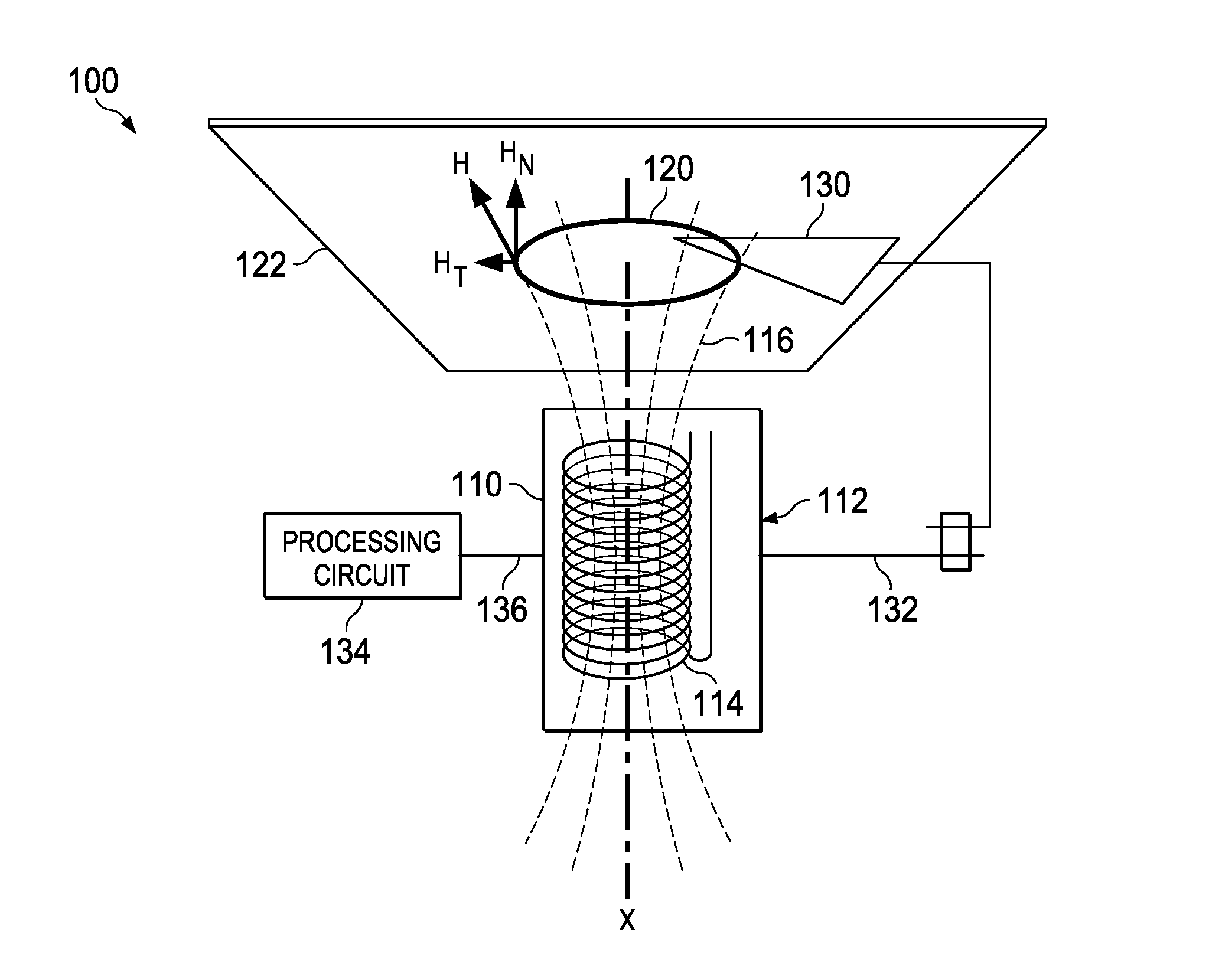
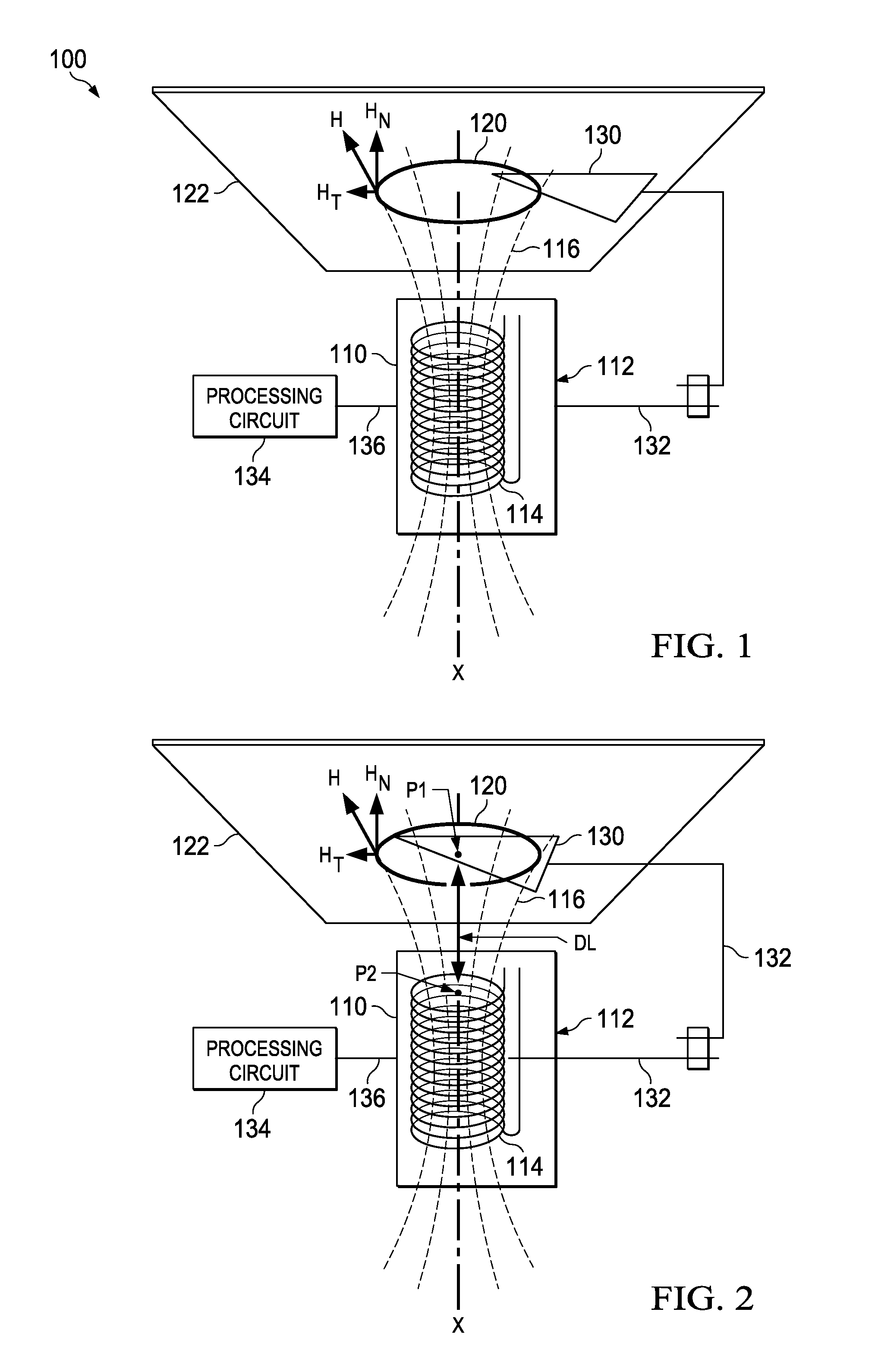
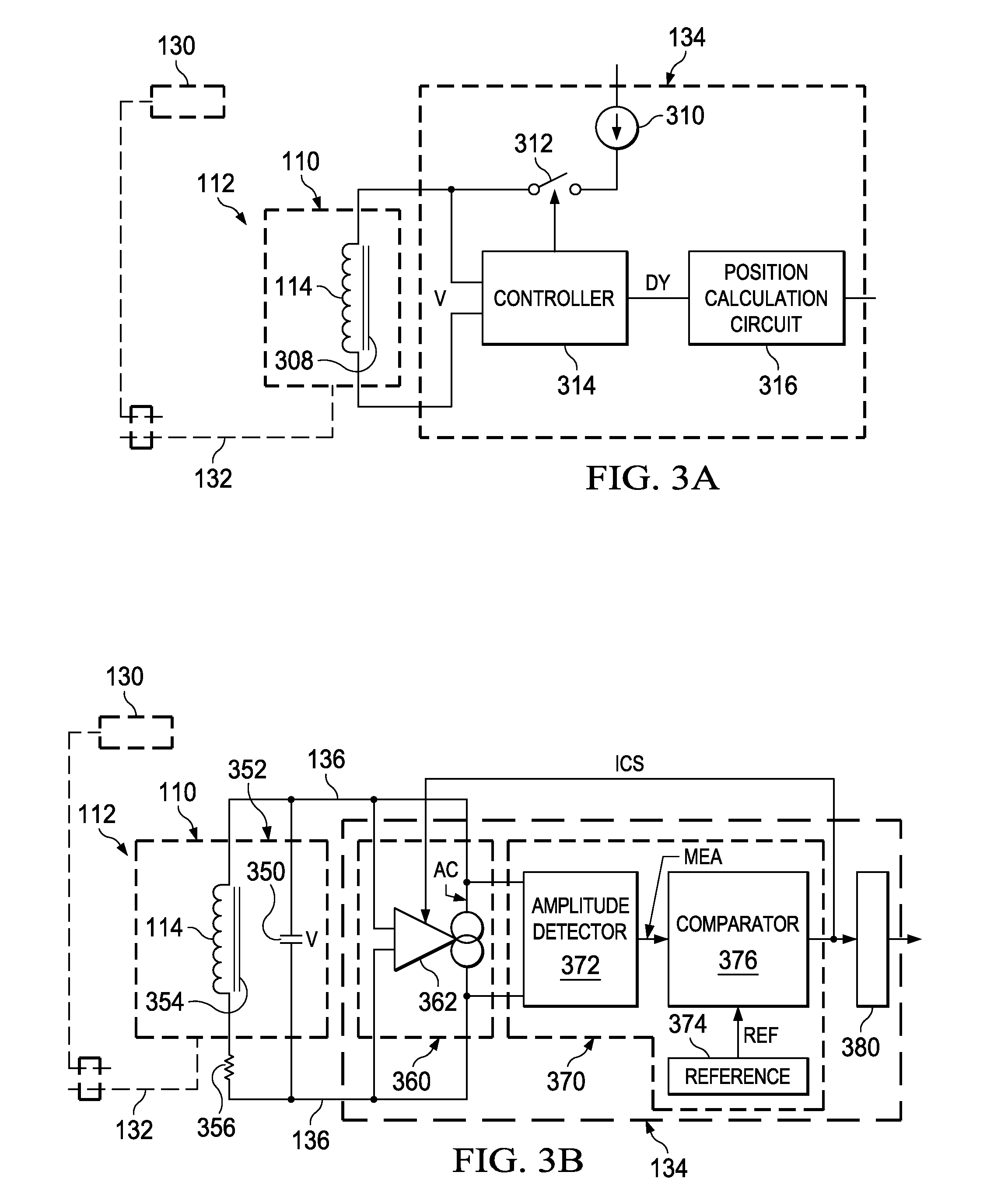
 In one embodiment, a first sensing domain area is established in a first target plane using first and second sensor coils disposed on a longitudinal axis, on opposite sides of the first target plane and connected in series, so that a series-combined inductance is a multiple of a sum of the respective first and second coil inductances. Target position within the first sensing domain area of the first target plane is detected based on the series-combined inductance of the first and second coils, which changes as the target moves within the first sensing domain area of the first target plane. Further sensitivity can be achieved by additional coils, series connected on the same longitudinal axis, each coil pair defining a sensing area on a respective target plane intermediate the coils.

Description

CROSS REFERENCE TO RELATED APPLICATION[0001]This application is a continuation-in-part of U.S. application Ser. No. 14 / 139,701 (Docket TI-73551), filed 12 / 23 / 2013, which claims priority to Provisional Application No. 61 / 772,290 filed on Mar. 4, 2013 for George Pieter Reitsma, Provisional Application No. 61 / 772,324 filed on Mar. 4, 2013 for George Pieter Reitsma et al., Provisional Application No. 61 / 838,084 filed on Jun. 21, 2013 for George Pieter Reitsma et al., and Provisional Application No. 61 / 877,759 filed on Sep. 13, 2013 for Jonathan V. Baldwin et al.BACKGROUND OF THE INVENTION[0002]1. Field of the Invention[0003]The present invention relates to inductive sensing systems, including systems based on resonant inductive sensing, such as for detecting position or proximity, or state or condition, of a target.[0004]2. Description of the Related Art[0005]An eddy current sensor is a position detecting system that commonly includes an inductor, a target, and a processing circuit. The...

Claims


Application Information

Patent Timeline
IPC IPC(8): G01D5/20
CPCG01D5/202G01D2205/775
Inventor REITSMA, GEORGE PIETERFOMIN, EVGENY
Owner TEXAS INSTR INC
Why Eureka
Try Eureka