Operating state circuit for an inverter and method for setting operating states of an inverter

a technology of operating state circuit and inverter, which is applied in the direction of motor/generator/converter stopper, electric device, dynamo-electric converter control, etc., can solve the problem braking torque is a hindrance, etc. problems, to achieve the effect of reducing the power required for towing an electrically driven vehicle, smooth coasting, and maintaining freewheeling mod

Active Publication Date: 2015-07-30
ROBERT BOSCH GMBH
View PDF0 Cites 14 Cited by
  • Summary
  • Abstract
  • Description
  • Claims
  • Application Information

AI Technical Summary

Benefits of technology

[0014]One advantage of this approach is that no energy input into the DC voltage intermediate circuit takes place, so that the freewheeling mode is able to be maintained longer. Since no braking torque occurs in freewheeling mode, for example, in the event of the occurrence of a malfunction during travel using an electrically driven vehicle, smoother coasting may result. In addition, the power required for towing an electrically driven vehicle is reduced. In some fault events, for example, in the event of a failure of the low-voltage supply, in the event of a failure of the low-voltage-side detection of the position of the rotor of the electric machine, in the event of a failure of other low-voltage-side electronic control components or other low-voltage malfunctions, the electrically driven vehicle may be pushed without having to overcome the braking torque of the electric machine in the active short-circuit state.
[0015]Advantageously, a load or thermal overload of the inverter in the active short-circuit state is prevented, since no short-circuit currents occur in freewheeling mode. This is then advantageous in p

Problems solved by technology

For example, if the car is towed,

Method used


Image

  • Operating state circuit for an inverter and method for setting operating states of an inverter
  • Operating state circuit for an inverter and method for setting operating states of an inverter
  • Operating state circuit for an inverter and method for setting operating states of an inverter

Examples


Embodiment Construction

[0028]In the figures, identical and functionally identical elements, features, and components are provided with the same reference numbers, unless stated otherwise. It is to be understood that for reasons of clarity, components and elements in the drawings are not necessarily depicted true to scale.

[0029]Additional possible embodiments and refinements and implementations of the present invention also include combinations of features of the invention described above or below which are not explicitly specified.

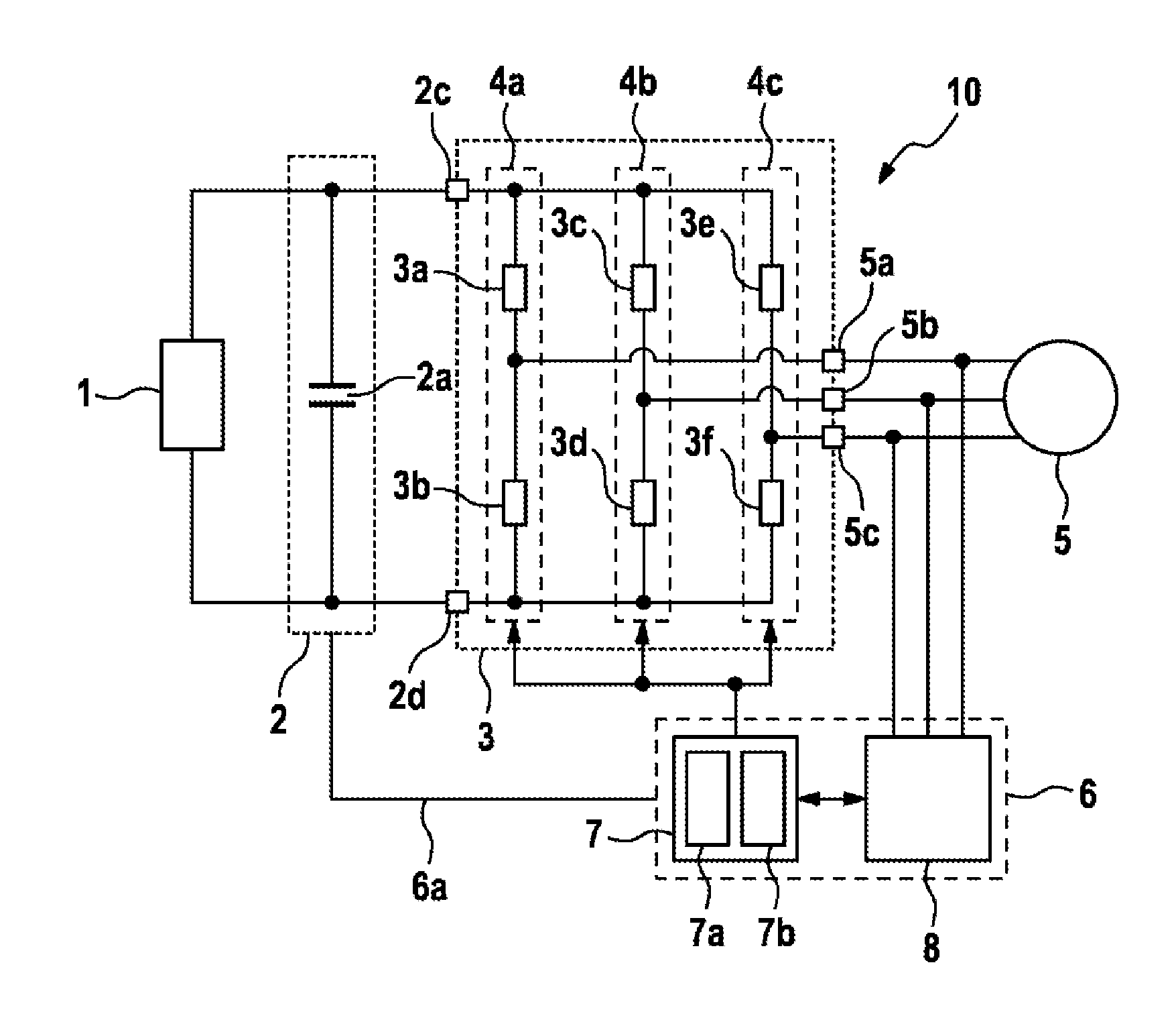
[0030]FIG. 1 shows a schematic representation of an electric drive system 10. The electric drive system 10 includes a high-voltage energy source 1, for example, a high-voltage source such as a traction battery, which is able to provide a supply voltage. The high-voltage energy source 1 may be designed in a drive system of an electrically driven vehicle, for example, as an energy store 1. It is also possible that the high-voltage energy source 1 is grid-based, i.e., that the elec...


PUM


Abstract

The invention relates to an operating state circuit for driving an inverter with half-bridges having respective switching devices, which inverter supplies an n-phase supply voltage to an n-phase electrical machine via phase connections associated with the respective half-bridges, where n≧1. The operating state circuit comprises an evaluation device, which is connected to the phase connections of the inverter and to input connections of the inverter and is designed to detect an input voltage of the inverter and phase currents at the phase connections of the inverter, and a drive device which is coupled to the evaluation device and is designed to switch the inverter from a short-circuit state to a freewheeling mode on the basis of the detected input voltage, wherein the evaluation device is designed to generate a freewheeling trigger signal and to output said signal to the drive device if the detected input voltage is lower than an adjustable freewheeling threshold value, and wherein the drive device is designed to change the respective switching devices of the half-bridges to an open state after receiving the freewheeling trigger signal only when the particular phase current detected at the associated phase connection has a zero crossing or a current direction coming from the inverter.

Description

BACKGROUND OF THE INVENTION[0001]The present invention relates to an operating state circuit for an inverter and a method for setting operating states of an inverter, in particular for an inverter for supplying power to a synchronous machine.[0002]Electric drives of hybrid or electric vehicles may include permanently excited electric machines, in particular synchronous machines, which are supplied with AC voltage by means of a pulse-controlled inverter. In the event of fault states on the low-voltage side, for example, in the event of a failure of the electronic control, the energy supply, various sensors, the data communication, or a fuse, it may be necessary to set a safe state in the inverter i.e., a switching state of the inverter in which safety remains ensured for persons accessing the vehicle such as first responders in the event of an accident, and for the integrity of the electrical system.[0003]Generally, a control device of the inverter is supplied by the low-voltage syst...

Claims


Application Information

Patent Timeline
IPC IPC(8): H02M7/537
CPCH02M7/537H02M7/5387H02M1/38B60L3/04H02P3/18H02P3/22H02M7/53875Y02T10/64
Inventor RAICHLE, DANIELSCHOENKNECHT, ANDREASEBERLEIN, EDWIN
Owner ROBERT BOSCH GMBH
Why Eureka
Try Eureka