Method and apparatus for ultra-low power switching microphone

a switching microphone, ultra-low power technology, applied in the field of methods and equipment, can solve the problem of increasing power consumption of digital mems microphones, and achieve the effect of reducing the average power consumption of an existing analog microphon

Active Publication Date: 2015-07-30
DSP GROUP
View PDF4 Cites 22 Cited by
  • Summary
  • Abstract
  • Description
  • Claims
  • Application Information

AI Technical Summary

Benefits of technology

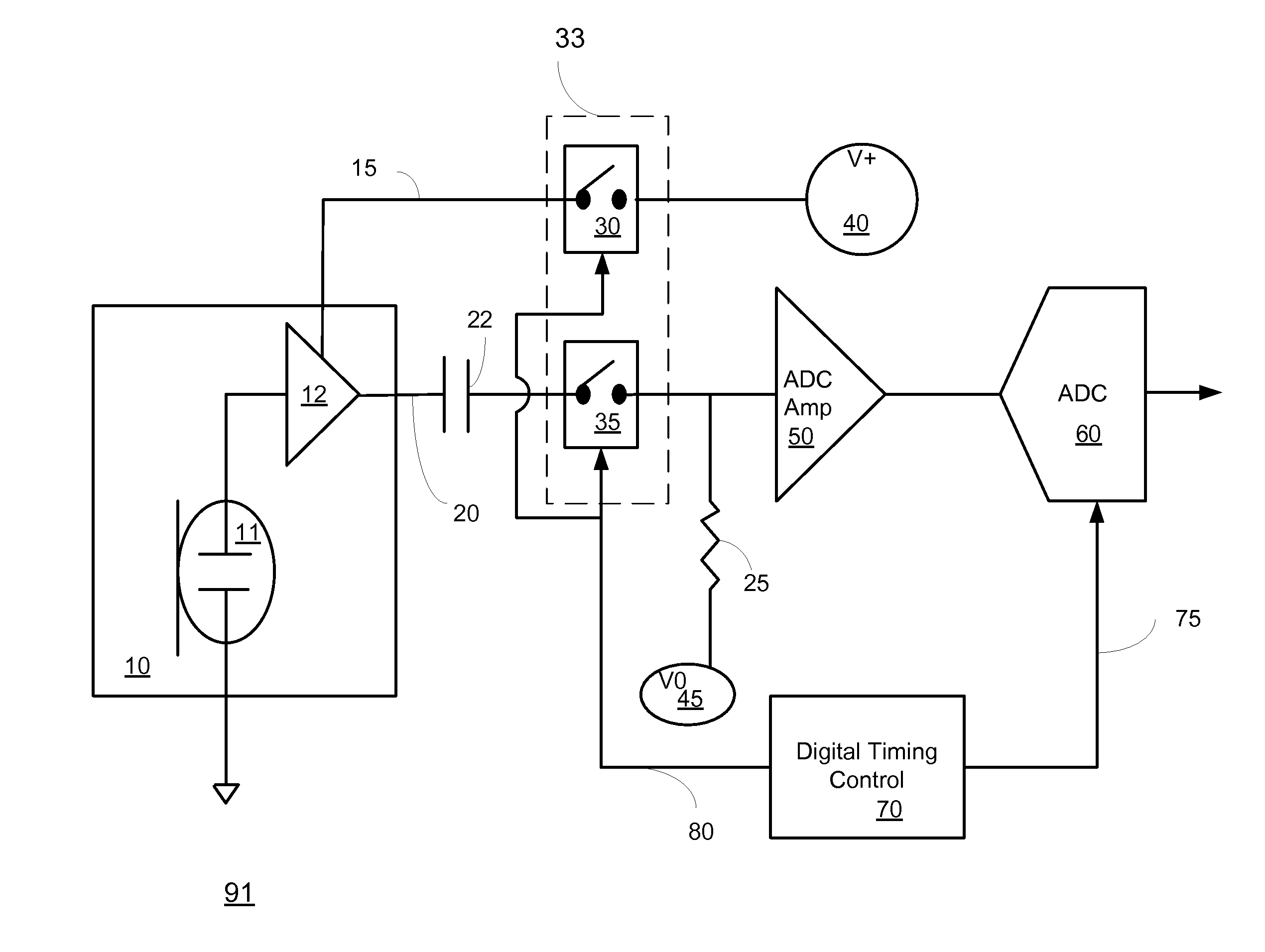
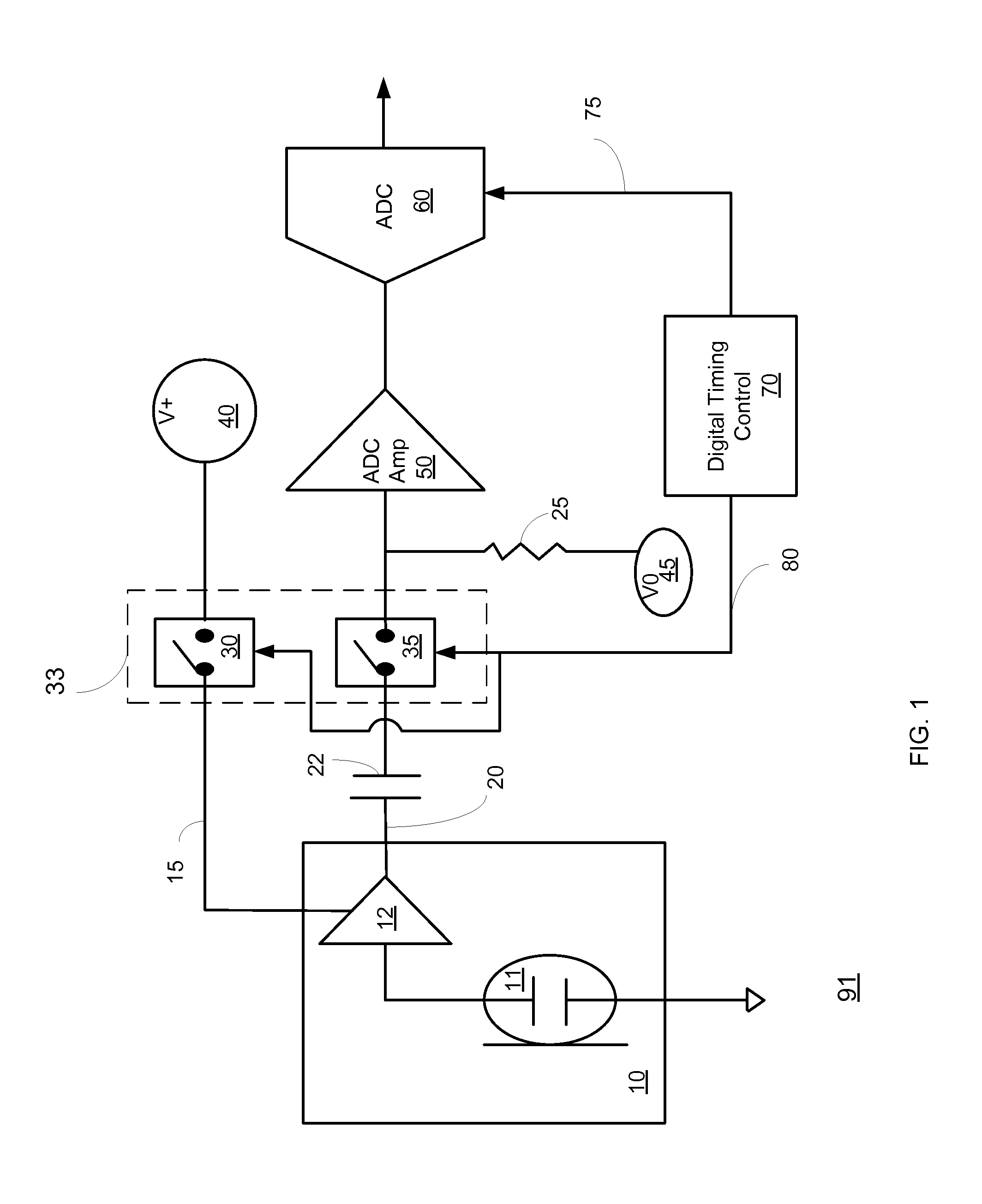
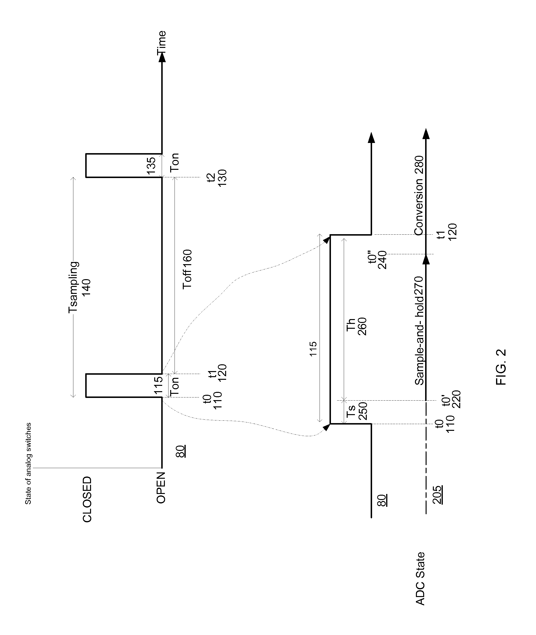
[0006]There is provided a device and a method for minimizing a power consumption of the analog parts of an analog microphone down to few micro watts (and even below) while still using existing analog microphones. A first power supply coupled to the analog microphone is repetitively provided (turned on) or prevented from being provided (turned off) in a cyclic manner that is synchronized with the ADC sampling rate. In this way the microphone amplifier, whether it is a J-FET transistor or an operational amplifier, is off most of the cycle time, and is turned on only for a few micro-seconds prior to the sample-and-hold timing of the ADC device. By this method, the average power consumption of an existing analog microphone can be reduced by a factor of 10 or more. A microphone amplifier is fed by a first power supply V+. An ADC amplifier that precedes the ADC is fed by a second power supply V0. A capacitor is coupled between an output of the analog microphone and an input of the ADC and provides DC isolation.

Problems solved by technology

Digital MEMS microphones consume more power as they also contain an integrated ADC in addition to the amplifier.

Method used


Image

  • Method and apparatus for ultra-low power switching microphone
  • Method and apparatus for ultra-low power switching microphone
  • Method and apparatus for ultra-low power switching microphone

Examples


Embodiment Construction

[0045]In the following detailed description, numerous specific details are set forth in order to provide a thorough understanding of the invention. However, it will be understood by those skilled in the art that the present invention may be practiced without these specific details. In other instances, well-known methods, procedures, and components have not been described in detail so as not to obscure the present invention.

[0046]The subject matter regarded as the invention is particularly pointed out and distinctly claimed in the concluding portion of the specification. The invention, however, both as to organization and method of operation, together with objects, features, and advantages thereof, may best be understood by reference to the following detailed description when read with the accompanying drawings.

[0047]It will be appreciated that for simplicity and clarity of illustration, elements shown in the figures have not necessarily been drawn to scale. For example, the dimensio...


PUM


Abstract

A scheme is described to switch the power supply to the MEMS microphone on and off in a cyclic manner that is synchronized with the associated ADC sampling rate. In this way the MEMS microphone amplifier, whether it is a J-FET transistor or an operational amplifier, is off most of the cycle time, and is turned on only for a few micro-seconds prior to the sample-and-hold timing of the ADC device. By this method, the average power consumption of an existing analog MEMS microphone can be reduced by a factor of 10 or more.

Description

RELATED APPLICATIONS[0001]This application claims the priority of US provisional patent serial number 61 / 933316 filing date Jan. 30, 2014 which is incorporated herein by reference in its entirety.FIELD OF THE INVENTION[0002]This invention relates to the field of microphones such as but not limited to MEMS (Micro Electrical-Mechanical System) microphones.BACKGROUND OF THE INVENTION[0003]A MEMS microphone is also called a microphone chip or silicon microphone. MEMS microphones are usually referred to as being of two main types: analog and digital. Both types are based on a membrane or diaphragm that is combined with a permanently charged capacitor that changes its capacitance according to the pressure derived from acoustic waves. This is commonly known as an electret microphone. The pressure-sensitive diaphragm is etched directly into a silicon chip by MEMS techniques, and is usually accompanied with a preamplifier; this is referred to as an ‘analog MEMS microphone’. To be more readil...

Claims


Application Information

Patent Timeline
Patent Type & Authority Applications(United States)
IPC IPC(8): H04R3/00
CPCH04R2201/003H04R3/00H04R1/04
Inventor HAIUT, MOSHE
Owner DSP GROUP
Why Eureka
Try Eureka