Thermal management system for vehicle

a technology of thermal management system and vehicle, applied in the direction of electric devices, battery/fuel cell control arrangement, transportation and packaging, etc., can solve the problems of complicated connection structure between the circulation circuit and the cooling circuit, complexity might become more significant, and the entire circuit configuration of the system might be complicated

Active Publication Date: 2015-08-06
DENSO CORP
View PDF0 Cites 68 Cited by
  • Summary
  • Abstract
  • Description
  • Claims
  • Application Information

AI Technical Summary

Benefits of technology

[0016]Therefore, the heat media circulating through the numerous flow paths can be switched with a simple structure in

Problems solved by technology

However, the entire circuit configuration of the system might be complicated.
Such complexity might become more significant as the number of cooling target devices is increased.
Together with the increase, the number of valves for connect

Method used


Image

  • Thermal management system for vehicle
  • Thermal management system for vehicle
  • Thermal management system for vehicle

Examples


first embodiment

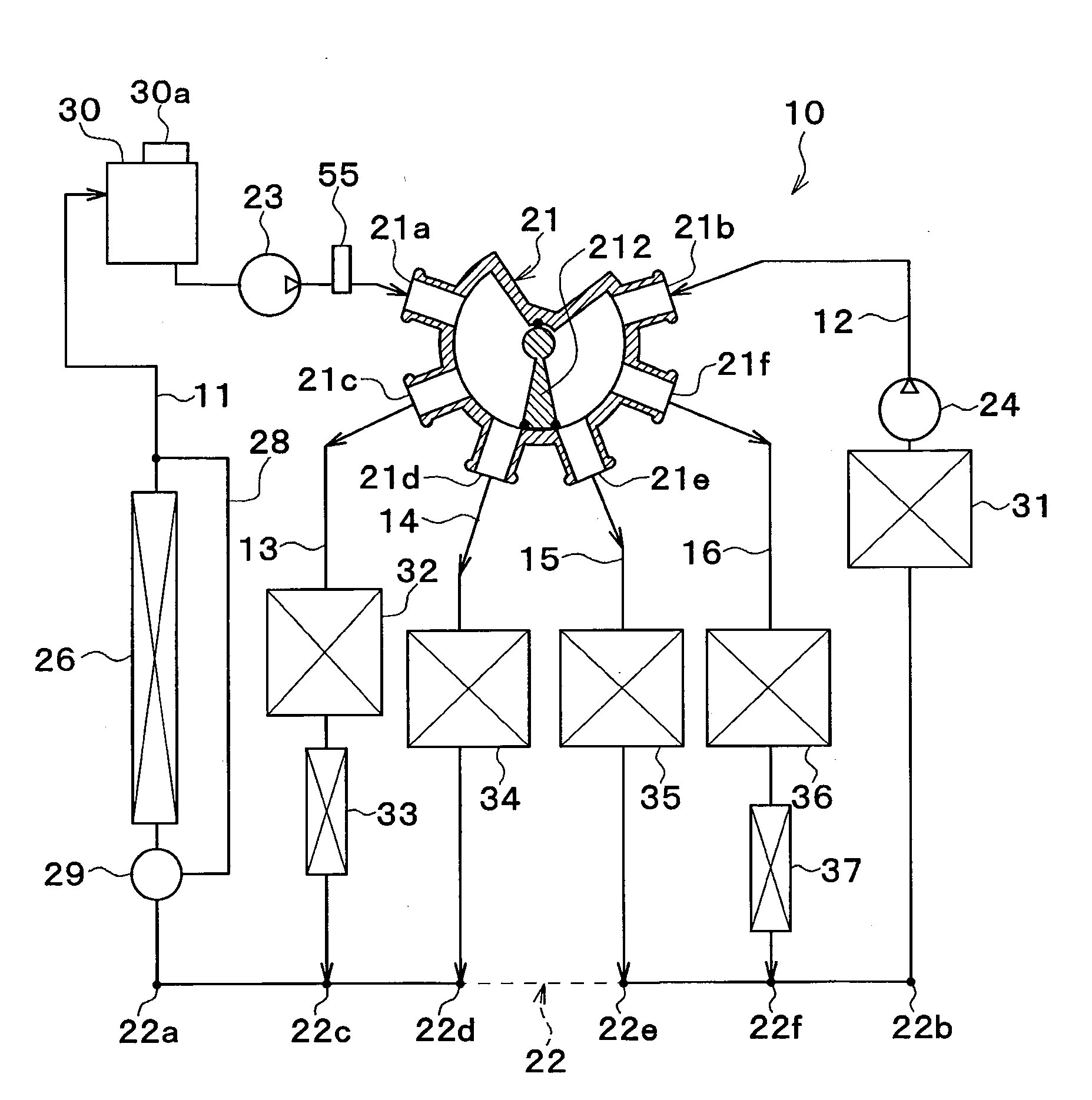
[0044]Now, a first embodiment of the invention will be described. A vehicle thermal management system 10 shown in FIG. 1 is used to cool various temperature adjustment target devices included in a vehicle (devices requiring cooling or heating) to an appropriate temperature.

[0045]In the embodiment, the thermal management system 10 is applied to a hybrid vehicle that can obtain the driving force for traveling from both an engine (internal combustion engine) and a motor for traveling.

[0046]The hybrid vehicle of the embodiment can switch between a traveling state (HV traveling) and another traveling state (EV traveling). In the HV traveling state, the vehicle travels by obtaining a driving force from both the engine and electric motor for traveling while the engine is operated or stopped according to a traveling load on the vehicle and a remaining electricity storage of a battery or the like. In the EV traveling state, the vehicle travels by obtaining a driving force only from the elect...

second embodiment

[0154]Referring to FIG. 19, the second embodiment differs from the above-mentioned first embodiment in devices disposed in the flow paths 11 to 16.

[0155]In the first flow path 11, the first pump 23, and the engine 60 and radiator 61 for the engine as the temperature adjustment target devices are arranged in parallel to each other. The first pump 23, the engine 60, and the radiator 61 for the engine constitute an engine coolant circuit indicated by thick solid lines of FIG. 19.

[0156]In the engine coolant circuit, a radiator bypass flow path 62 and a thermostat 63 are disposed. The radiator bypass flow path 62 is a flow path through which the coolant flows while bypassing the radiator 61 for the engine. The thermostat 63 switches between the flow of the coolant through the radiator 61 for the engine and the flow of the coolant through the radiator bypass flow path 62 in accordance with the temperature of the coolant.

[0157]In the first flow path 11, the coolant temperature sensor 55 is...

third embodiment

[0168]Referring to FIG. 20, a third embodiment of the invention differs from the above-mentioned second embodiment in devices disposed in the flow paths 11 to 16.

[0169]In the first flow path 11, the radiator 61 for the engine is disposed. In the second flow path 12, the second pump 24 and the radiator 26 are disposed in series with each other. In the third flow path 13, the first pump 23 and the engine 60 are disposed in series with each other. In the third flow path 13, the coolant temperature sensor 55 is disposed on the downstream side directly under the engine 60. In the fourth flow path 14, the heater core 33 and the oil heat exchanger 34 are disposed in series with each other. In the fifth flow path 15, the intercooler 64 is disposed. In the sixth path 16, the inverter 35 is disposed.

[0170]Now, the operation of the above-mentioned structure will be described. During the EV traveling mode or immediately after the start-up of the engine, the valve body 212 of the switching valve...


PUM


Abstract

A first-pump arrangement flow path, temperature-adjustment target-device arrangement flow paths, and a second-pump arrangement flow path are connected to a communication flow path in this order from one end side to the other end side of the communication flow path. A first heat exchanger is disposed in the first-pump arrangement flow path among numerous flow paths, which is connected to the communication flow path at a position on a side of the first-pump arrangement flow path, rather than the flow path in which a second heat exchanger is disposed. The switching portion is operated to establish communication between plural flow paths, starting from the flow path connected to the communication flow path at the position closest to the one end side among the numerous flow paths, up to the flow path connected to the communication flow path at an n-th position counted from the one end side among the numerous flow paths.

Description

CROSS REFERENCE TO RELATED APPLICATION[0001]This application is based on a Japanese Patent Application 2012-187152 filed on Aug. 28, 2012, the contents of which are incorporated herein by reference in its entirety.FIELD OF THE INVENTION[0002]The preset disclosure relates to a thermal management system used for a vehicle.BACKGROUND ART[0003]Conventionally, as disclosed in Patent Document 1, there is proposed a heat controller for cooling a motor generator, an inverter, a battery and a vehicle interior of an electric car.[0004]The heat controller in the related art includes a cooling circuit for circulation of a coolant used for cooling the motor generator and the inverter, a first circulation circuit for circulation of a coolant used for cooling the battery and vehicle interior, and a second circulation circuit for circulation of a coolant exchanging heat with outside air through an exterior heat exchanger.[0005]Further, the heat controller includes a first valve for disconnecting be...

Claims


Application Information

Patent Timeline
IPC IPC(8): B60H1/00B60H1/03
CPCB60H1/00878B60H1/03B60L11/1874B60L2240/34B60L2240/36B60L2240/425B60L2240/525B60L2240/545B60K11/02B60L1/003B60L1/02B60H1/08B60H1/22Y02T10/7005Y02T10/705Y02T10/642B60H1/00271B60H1/00278B60H1/00385B60L3/00Y02T90/16B60L58/26Y02T10/64Y02T10/70F16K11/076
Inventor ENOMOTO, NORIHIKOKAKEHASHI, NOBUHARUNISHIKAWA, MICHIO
Owner DENSO CORP
Why Eureka
Try Eureka