Battery reinforced polymer composite smart structure

a composite structure and reinforced polymer technology, applied in the field of lithium ion batteries, can solve the problems of battery addition, unsuitability for most applications, and inability to easily integrate traditional liquid electrolyte libs into the structure of reinforced polymer composites, and achieve high stiffness and strength, and dimensional stability to the composite structure

Inactive Publication Date: 2015-08-06
KALPTREE ENERGY
View PDF4 Cites 12 Cited by
  • Summary
  • Abstract
  • Description
  • Claims
  • Application Information

AI Technical Summary

Benefits of technology

[0008]The battery element thus formed is surrounded by a polymer matrix material, which may consist of thermoplastic or thermosetting resin. In particular, individual battery elements within a laminate may be connected together such that the outermost (negative) electrode current collectors are in physical contact and connected to an external (negative) terminal, while all substrate ends may be connected at an external (positive) terminal. Alternatively, individual battery elements within a laminate may be connected together such that the outermost (negative) electrode current collectors are connected together using an electrical conductive wire and connected to the external negative terminal, while all substrate ends are connected at the external positive terminal. The laminate can be in woven cloth form. The reinforcing battery provides a high stiffness and strength, as well as dimensional stability to the composite structure. Preferably, the battery volume fraction will comprise about 50% to 90% of the overall volume of the composite structure.
[0009]The laminate structure may be stacked with battery elements having alternately (1) thinner active layers to increase device power density (power laminate) and (2) with thicker active layers to increase device energy density (energy laminate). Every individual battery elements within a given individual layer of the laminate may be of the same length-to-diameter aspect ratio, but the diameters of their respective substrates can vary from 10 μm to 100 μm to increase the packing density of the bundle or the thicknesses of the battery active layers can vary to increase the charge-discharge rate. The battery reinforced polymer composite can be fabricated by stacking individual battery reinforced laminates in a predetermined molded shape.

Problems solved by technology

However, batteries add significant weight and volume to devices.
However, traditional liquid electrolyte LIBs cannot easily be integrated within the structure of reinforced polymer composites due to limitations imposed by the high curing temperatures of reinforced polymer composite.
However significant weight fraction of inactive passive material components, such as the packaging, makes traditional SSBs unsuitable for most applications.
Additionally, these SSBs do not act as a load bearing component of structure as the transverse strength properties of the flat substrate being used are typically poor.

Method used


Image

  • Battery reinforced polymer composite smart structure
  • Battery reinforced polymer composite smart structure
  • Battery reinforced polymer composite smart structure

Examples


Embodiment Construction

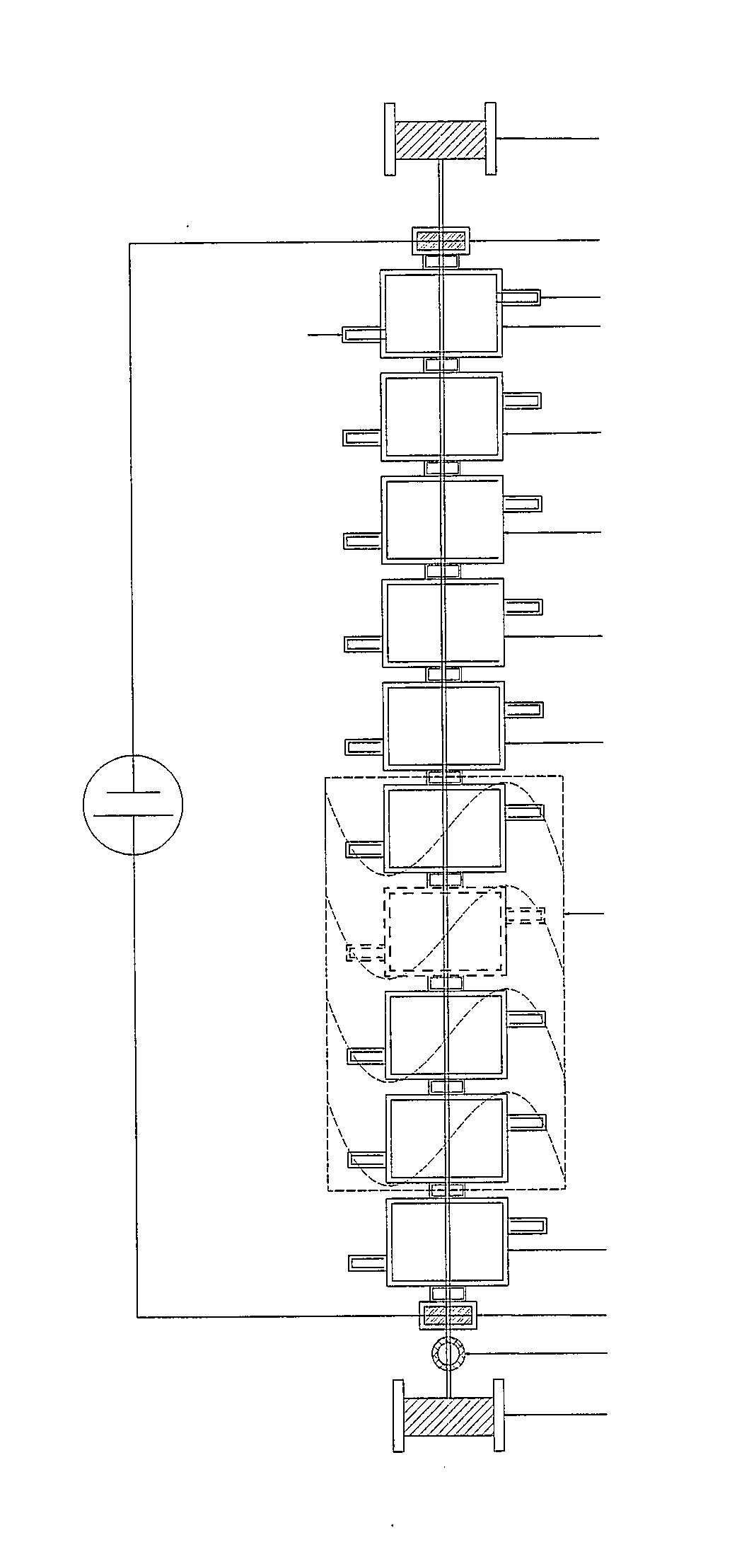
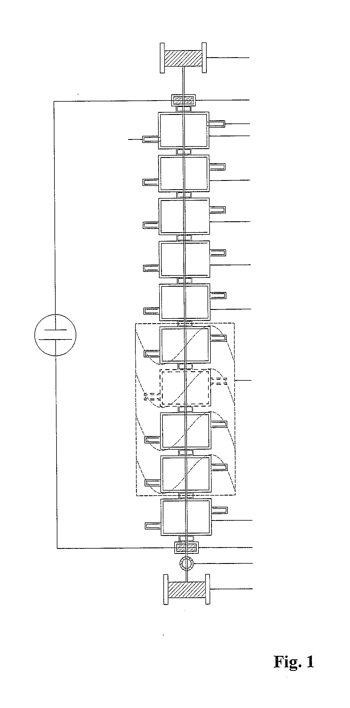
[0017]An embodiment of the present invention relates to using a thermal chemical vapor deposition process (TCVD) to nucleate and sequentially grow concentric layers of cathode, electrolyte, anode and anode current collector onto an electrically conductive solid substrate with a circular cross-sectional. The electrically conductive substrate acts as a current collector for the cathode during battery charging and discharging. In this embodiment, deposition of the anode layer onto the electrolyte layer allows outwardly volumetric expansion of anode constituents during the intercalation-deintercalation processes. (Note: in other embodiments the cathode and anode layers may be reversed.) One further advantage of concentric layer deposition over a circular substrate is that it minimizes mechanical stress non-uniformities within the deposited material as compared to flat substrates used in traditional SSB fabrication.

[0018]As seen in FIG. 1, a vertical TCVD tubular deposition apparatus (re...


PUM

PropertyMeasurementUnit
diametersaaaaaaaaaa
diametersaaaaaaaaaa
volume fractionaaaaaaaaaa

Abstract

A battery having a laminate structure of alternating layers of polymer matrix material and solid-state battery elements is fabricated. Individual solid-state battery elements are created in a deposition apparatus, each battery element having successive solid-state thin films concentrically formed over a conductive wire substrate to define anode, electrolyte and cathode active layers sandwiched between inner and outer current collectors. Inner current collectors are electrically coupled to each other (and likewise the outer current collectors) such that battery elements are connected in a specified series and parallel arrangement. Sets of the individual battery elements are laid upon cloth layers such that outer current collectors of the battery elements physically contact the cloth and the cloth layers are impregnated with selected thermoplastic or thermosetting resin, the impregnated cloth layers and their respective contacting battery elements are stacked to form a composite laminate. The laminate is compacted and cured, and the battery elements of the various layers are coupled to external electrodes. The battery elements double as load components for the laminate structure.

Description

CROSS-REFERENCE TO RELATED APPLICATION[0001]This application claims priority under 35 U.S.C. 119(e) from U.S. provisional application Ser. No. 61 / 935,440 filed Feb. 4, 2014.TECHNICAL FIELD[0002]The present invention relates to lithium ion batteries, particularly those of the solid-state type, and together with associated load-bearing structural elements.BACKGROUND ART[0003]Rechargeable lithium ion batteries (LIBs) are widely used in various kinds of portable electronic devices, medical devices and power tools and are being considered for use in electric vehicle. However, batteries add significant weight and volume to devices. The consolidation of battery and structure can reduce the total weight by exploiting the battery components as load-bearing elements and by eliminating battery fittings or supports. However, traditional liquid electrolyte LIBs cannot easily be integrated within the structure of reinforced polymer composites due to limitations imposed by the high curing temperat...

Claims


Application Information

Patent Timeline
Patent Type & Authority Applications(United States)
IPC IPC(8): H01M10/04H01M10/0587H01M10/0565H01M50/406
CPCH01M10/0431H01M10/0525H01M10/0587H01M10/0565H01M4/139H01M10/0472H01M10/0562H01M10/058H01M10/0585H01M6/42Y10T29/49115Y02E60/10Y02P70/50H01M50/406
Inventor UPADHYAYA, DEEPAKISAACSON, MARKSWORD, MICHAEL D.HITCHAN, GREGORY D.VAN MUIJEN, BROOK E.
Owner KALPTREE ENERGY
Why Eureka
Try Eureka