Volume measuring device and volume measuring method

a technology of volume measurement and measuring device, which is applied in the direction of liquid/fluent solid measurement, instruments, machines/engines, etc., can solve the problems of pressure variation and inability to accurately measure acoustic pressure, and achieve the effect of accurate and convenient inspection of the volume of the cylinder

Inactive Publication Date: 2015-08-13
MAGINEERING INC
View PDF5 Cites 3 Cited by
  • Summary
  • Abstract
  • Description
  • Claims
  • Application Information

AI Technical Summary

Benefits of technology

[0019]The volume measuring method allows an accurate and convenient inspection of the cylinder volume in a factory line of the reciprocating engine.

Problems solved by technology

However, the first and second methods may have disadvantages that the pressure variation and the acoustic pressure cannot be measured accurately because the air leak may occur at a gap around the piston ring and the combustion chamber may not be a completely closed object.
The third method has a disadvantage for use in a factory line because it is necessary to disassemble the cylinder main body.

Method used


Image

  • Volume measuring device and volume measuring method
  • Volume measuring device and volume measuring method
  • Volume measuring device and volume measuring method

Examples


first embodiment

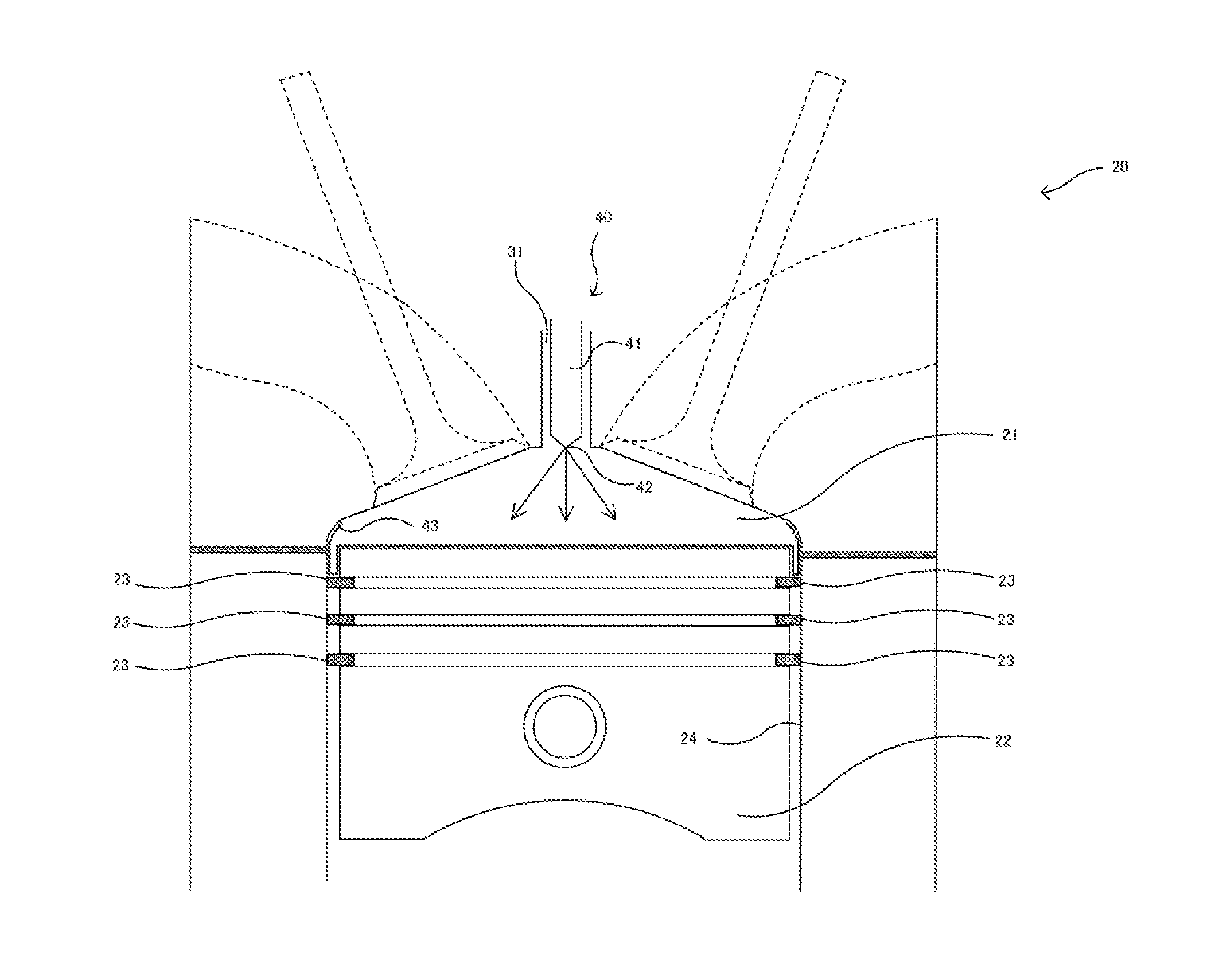
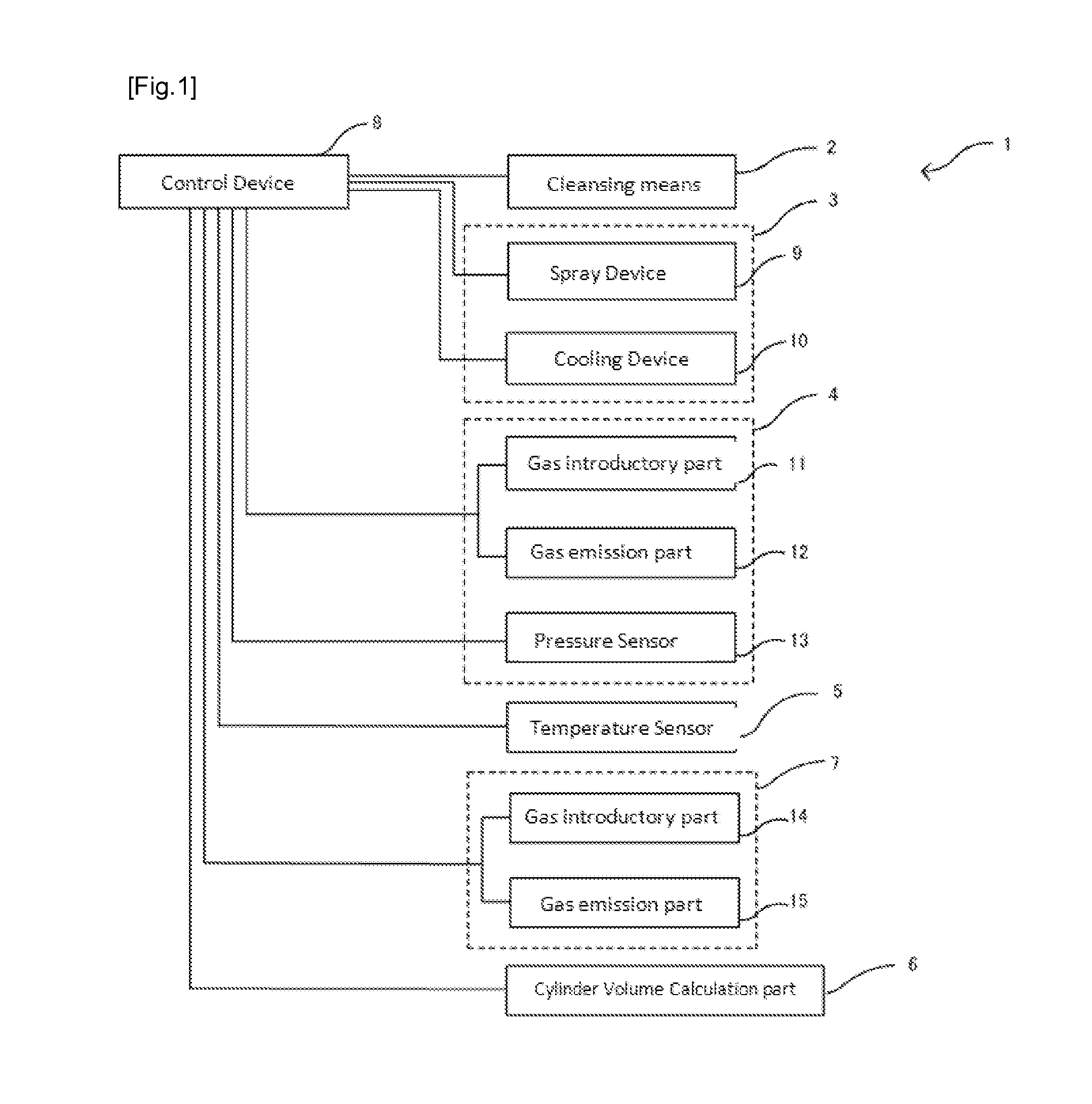
[0027]The present embodiment relates to volume measuring device 1 for measuring cylinder volume in an internal-combustion engine of a reciprocation engine. Volume measuring device 1 has cleansing means 2, coating formation means 3, pressure measurement means 4, temperature sensor 5, cylinder-volume calculation means 6, elimination means 7, and control means 8. Coating formation means 3 has spraying device 9 and cooling device 10. Pressure measurement means 4 has gas introductory part 11, gas emission part 12, and pressure sensor 13.

[0028]Volume measuring device 1 cleanses inside the cylinder using cleansing means 2 and then coats a portion of or entire inner surface of a cylinder with pyrolytic resin using spraying device 9 of coating formation means 3. The coated pyrolytic resin is cooled by cooling device 10, and the coating is thereby formed. A fixed quantity of gas is then introduced inside the cylinder, where the coating is formed therein, from gas introductory part 11. Or othe...

second embodiment

[0046]The following embodiment can be contemplated. The portion which is common to the first embodiment will not be described in detail.

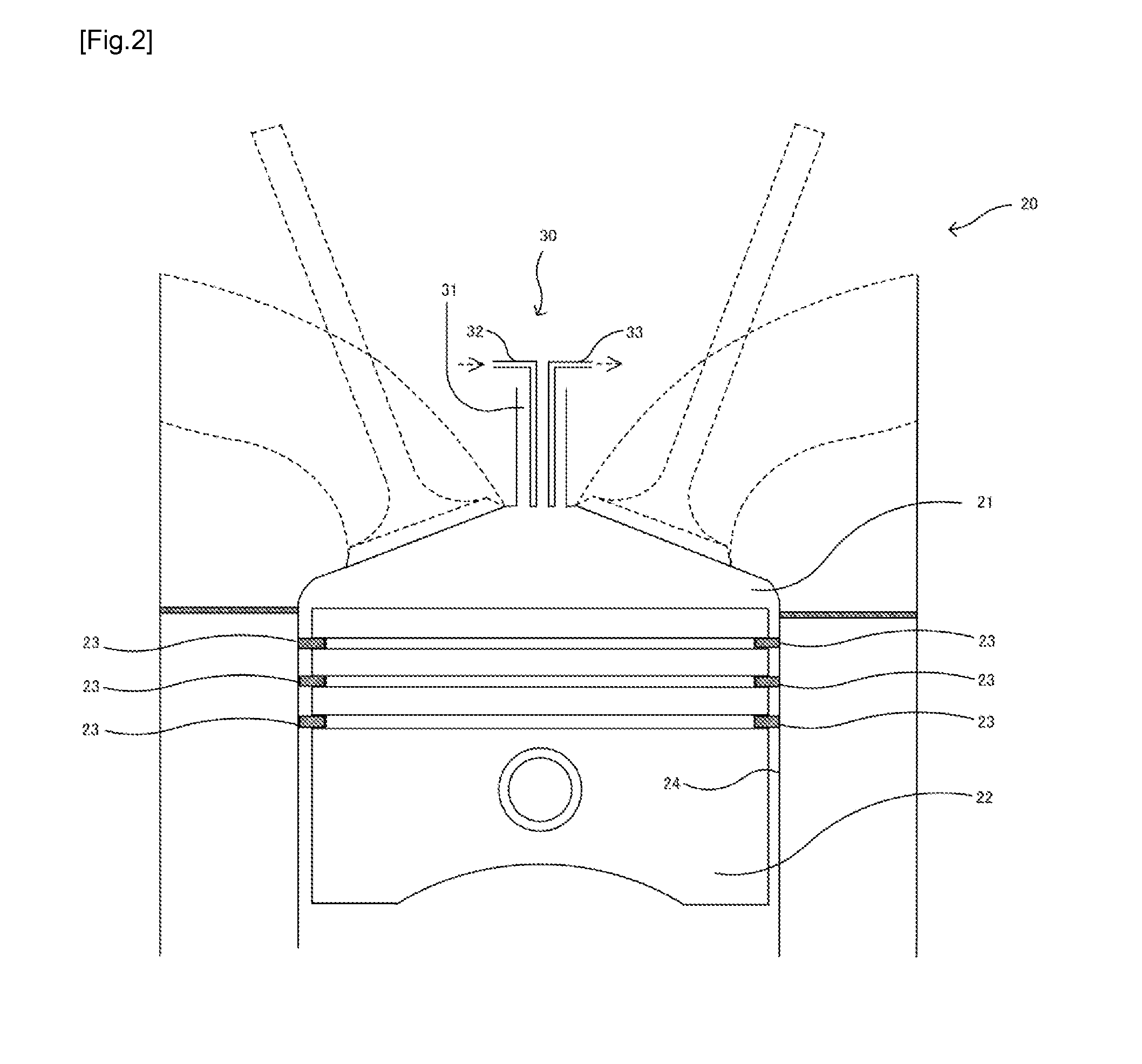
[0047]In volume measuring device 1 of the first embodiment, cleansing means 2, coating formation means 3 and pressure measurement means 4 are replaced for respective process. Instead, a device which equips all of these means can be attached as shown in FIG. 6 can be used. This eliminates the need of replacement but can achieve the same function. Volume measuring device 1 of the present invention allows an efficient measurement of cylinder volume by such configuration.

[0048]In this embodiment, gas introduction / emission of cleansing means 2, pressure measurement means 4, and elimination means 7 are made by single device as shown in FIG. 6. As cleansing means 2, high temperature and high pressure gas are introduced in the cylinder 21 from gas introductory part 70. Here, gas emission part 71 may be opened and adjusted so that the cleansing can be done e...


PUM


Abstract

The volume measuring device has a coating forming means which, using pyrolytic resin, forms a coating on either part or all of the inner surface of the cylinder; a pressure measuring means which introduces a fixed quantity of gas into the cylinder in which the coating has been formed, or derives a fixed quantity of gas from the inside of the cylinder, and measures the pressure within the cylinder before and after the introduction/derivation; and a volume calculating means which uses the pressure value obtained by the pressure measuring means to calculate the volume of the cylinder.

Description

TECHNICAL FIELD[0001]The present invention relates to a volume measuring device and volume measuring method.BACKGROUND[0002]There are several known methods for measuring a cylinder volume of the combustion chamber of a reciprocation engine when a piston is at top dead center. The first method is to utilize the volume and pressure change of the medium inside the combustion chamber (JP H04-198833A, JP H06-082342A). The second method is an acoustic volume measuring method using a Helmholtz resonator (JP H06-186070A). The third method is to measure the quantity of the oil needed to fill the hollowed portion of the cylinder main body that is surrounded by the piston positioned at the top dead center and cylinder head. However, the first and second methods may have disadvantages that the pressure variation and the acoustic pressure cannot be measured accurately because the air leak may occur at a gap around the piston ring and the combustion chamber may not be a completely closed object. ...

Claims


Application Information

Patent Timeline
Patent Type & Authority Applications(United States)
IPC IPC(8): G01F17/00F02F11/00F02F1/18
CPCG01F17/00F02F11/00F02F1/18G01M15/05
Inventor IKEDA, YUJI
Owner MAGINEERING INC
Why Eureka
Try Eureka