Chassis Component Comprising a Stop for an Eccentric Disc

a technology of eccentric discs and chassis components, which is applied in the direction of resilient suspensions, vehicle components, fastening means, etc., can solve the problems of unsatisfactory known solutions, risk of unintentional crack formation and crack propagation in the basic material of the chassis component, and relatively complex compliance with the maximum permissible tolerances, etc., to achieve low degree of basic material deformation, increase the protection against crack formation, and the effect of low basic material deformation

Active Publication Date: 2015-08-20
AUTOTECH ENG DEUT
View PDF10 Cites 3 Cited by
  • Summary
  • Abstract
  • Description
  • Claims
  • Application Information

AI Technical Summary

Benefits of technology

[0013]A further preferred configuration of the solution according to the invention is characterised in that the greatest depth of the recess is less than 3.0 times, preferably less than 2.8 times, the thickness of the basic material. This configuration contributes to a very low degree of deformation of the basic material and thus increases the protection against crack formation. Alternatively or in addition, the depth of the recess of the chassis component according to the invention is determined according to the thickness of the eccentric disc, such that the depth of the recess is then, for example, 0.5 times to 1.2 times the thickness of the eccentric disc.
[0014]According to a further preferred configuration of the invention, each of the two oblong surfaces, extending in parallel with one another, has a length which is at least 0.8 times, preferably at least 1.1 times, the length of the slot. A sufficiently large adjustment region for the steering bar connection for setting the track and camber can thereby be achieved with a low degree of deformation of the basic material.
[0015]With regard to small dimensions of the recess and a low degree of deformation of the basic material, it is further advantageous if, according to a further preferred configuration of the invention, each of the two oblong surfaces (stop surfaces) extending in parallel with one another transitions into the base of the recess with a transition radius of less than 1.0 mm, preferably less than 0.6 mm.
[0016]A further advantageous configuration of the invention is characterised in that the peripheral edge region comprises two arcuate edge regions which transition into the two oblong surfaces extending in parallel with one another and comprise curved flanks in a sectional plane extending perpendicularly to the longitudinal axis of the slot, each of the flanks comprising a concave flank portion beginning at the base of the recess and a convex flank portion connected thereto and ending at the outer peripheral line of the peripheral edge region. The arcuate edge portions and the curved flanks thereof only require a relatively small amount of stretching or compression of the basic material when moulding the recess and thus contribute significantly to the prevention of crack formation. Preferably, the recess is formed in such a way that the convex flank portion has a curve length which is at least 20%, more preferably at least 80%, longer than that of the concave flank portion. Preferably, the flank section is formed on the two arcuate edge portions in such a way that the maximum possible inclination gradient of the entire flank section is as low as possible there.
[0017]With regard to simple assembly and adjustment of the eccentric disc, it is advantageous if, according to a further configuration of the invention, the concave flank portion begins at a distance from the longitudinal axis of the slot which is greater than the length of the slot.

Problems solved by technology

However, these known solutions are not satisfactory.
In the case of the slotted openings, there is a risk of unintentional crack formation and crack propagation in the basic material of the chassis component.
Moreover, it is relatively complex to comply with the maximum permissible tolerances with regard to the shape and the dimensions of the slotted openings.
In addition, it is possible, namely when tightening the screw connection, that indentations are formed on the slotted openings, and therefore the stop function is lost.
Forming the eccentric stop by welding on a supplementary element entails additional material costs and significant process costs due to the additional production step of welding.
Moreover, there is sometimes the risk of the supplementary element becoming detached if the welded joint is poorly produced and / or if it is subjected to corrosion.

Method used


Image

  • Chassis Component Comprising a Stop for an Eccentric Disc
  • Chassis Component Comprising a Stop for an Eccentric Disc
  • Chassis Component Comprising a Stop for an Eccentric Disc

Examples


Embodiment Construction

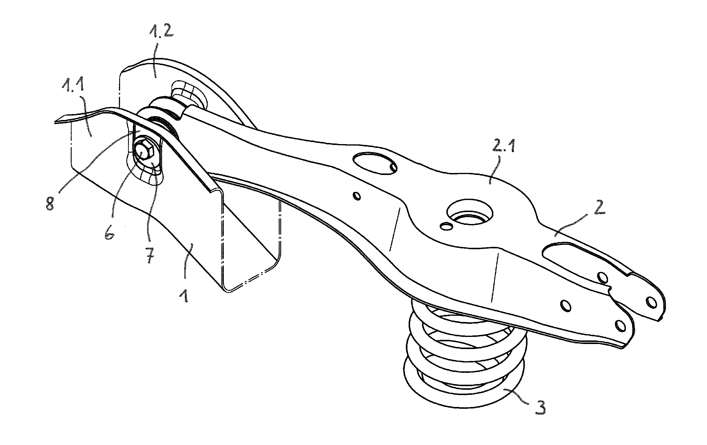
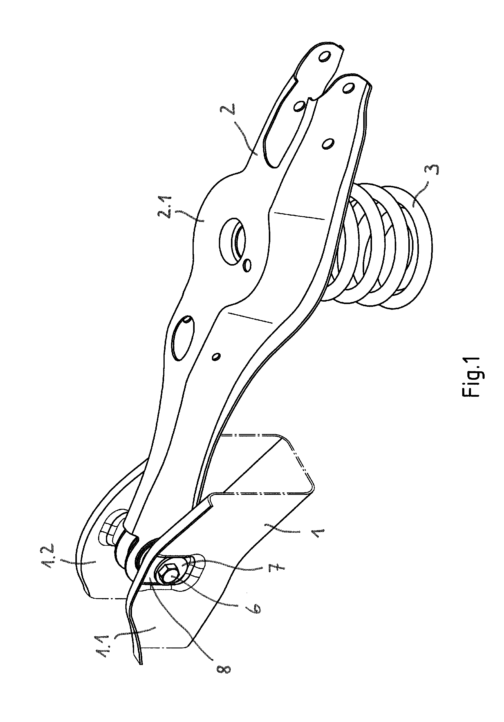
[0024]FIG. 1 shows a portion of a rear axle beam 1, on which a steering arm 2 for suspending a vehicle wheel is movably mounted. The steering arm (control arm) 2 is formed as a spring link and accordingly has a portion 2.1 having an enlarged diameter for receiving and supporting a helical spring 3. The rear axle beam 1 is formed of sheet metal, preferably sheet steel, which is shaped accordingly. Said beam is preferably produced from high-strength steel, in particular multiphase- or complex phase steel, which has a tensile strength of at least 800 MPa and a yield strength of at least 680 MPa for example.

[0025]The sheet thickness of the rear axle beam 1 is for example in the range of from 1.5 to 3.5 mm, preferably in the range of from 1.5 to 2.5 mm.

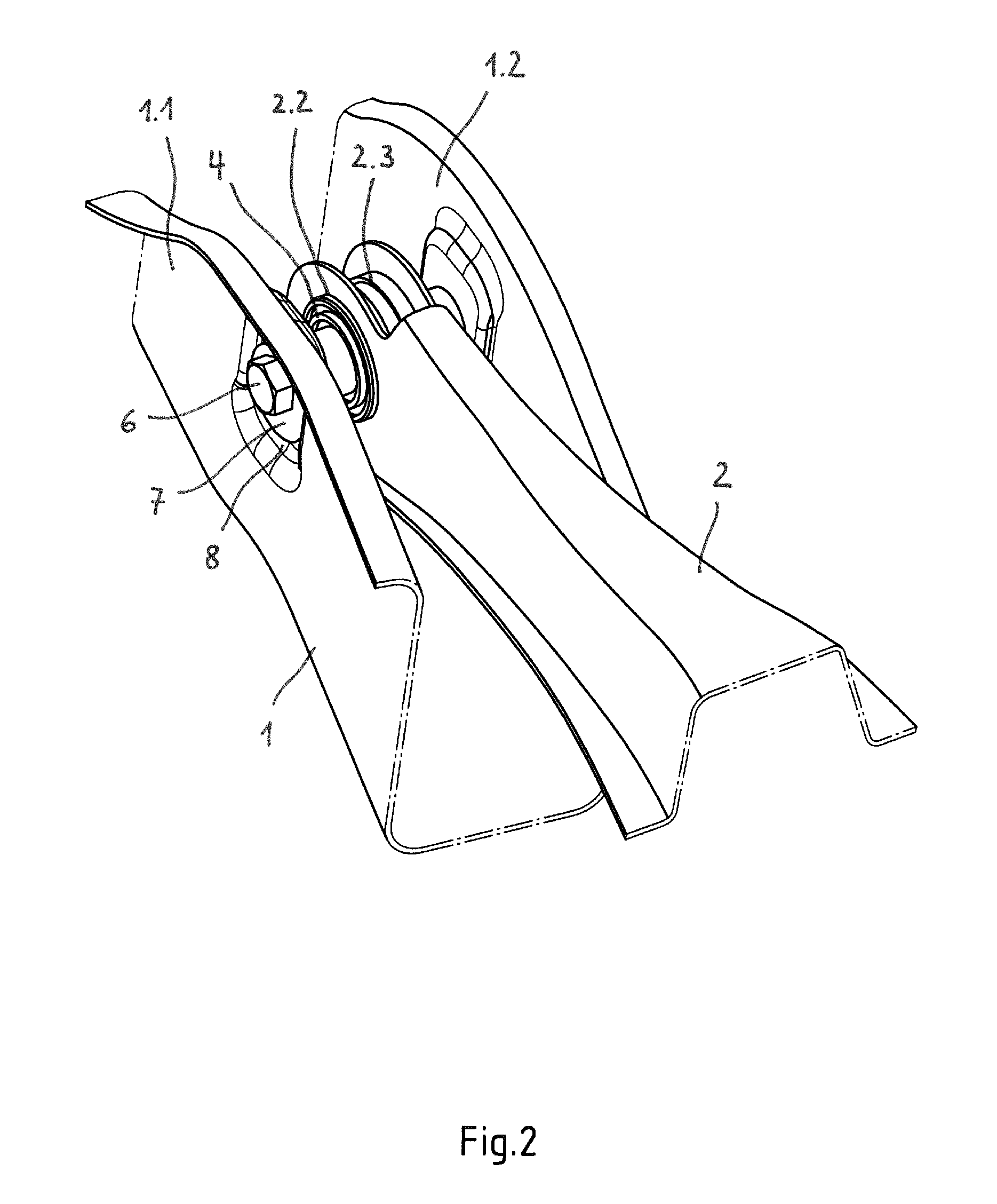
[0026]The end of the steering arm (control arm) 2 connected to the rear axle beam 1 comprises two bearing eyes 2.2, 2.3 which are aligned with one another and in which a bearing bush 4 is held in an interlocking manner. The bearing bush 4 ...


PUM


Abstract

The invention relates to a chassis component having a mount which is produced from a formable basic material and includes at least one slot for receiving a connection bolt for connecting a steering arm and at least one stop for an eccentric disc which is or can be connected in a torsionally stiff sense to the connection bolt. In order for it to be possible to produce the stop for the eccentric disc in a reliable and cost-effective manner without the risk of crack formation, the invention provides for a recess to be moulded into the basic material, which recess defines a peripheral edge region and a base enclosed by the edge region, the base including the slot and the edge region including two oblong surfaces extending in parallel with one another which act as the stop for the eccentric disc.

Description

CROSS-REFERENCE TO RELATED APPLICATION[0001]This application claims priority to European Patent Application No. 14155903.9 filed Feb. 20, 2014, the disclosure of which is hereby incorporated in its entirety by reference.BACKGROUND OF THE INVENTION[0002]1. Field of the Invention[0003]The invention relates to a chassis component having a mount which is produced from a formable basic material, preferably sheet steel and comprises at least one slot for receiving a connection bolt for connecting a steering arm and at least one stop for an eccentric disc which is or can be connected in a torsionally stiff sense to the connection bolt.[0004]2. Description of Related Art[0005]Chassis components of this type, for example rear axle beams, are provided on the mounts for connecting steering arms, in particular spring links and track rods for example, with means for setting the track and camber of the chassis wheels. Said means usually comprise an eccentric disc which is connected in a torsional...

Claims


Application Information

Patent Timeline
Patent Type & Authority Applications(United States)
IPC IPC(8): B60G7/00
CPCB60G7/001F16B5/0225B60G2204/143B60G2204/4302B60G2204/61B60G2206/10B60G2206/601B60G7/008
Inventor KLAASSEN, DENISKROLO, MARIOOLIVARES, MONTEJO
Owner AUTOTECH ENG DEUT
Why Eureka
Try Eureka